19
LP-520 REV. 5.1.17
6. After it has been determined that each appliance remaining connected to common venting system properly vents when tested as
outlined, return doors, windows, exhaust fans, fireplace dampers and any other gas burning appliance to their previous condition of use.
7. Any improper operation of the common venting system should be corrected so the installation conforms to the National Fuel Gas
Code, ANSI Z223.1. When resizing any portion of the common venting system, the common venting system should be resized to
approach the minimum size as determined using the appropriate tables in Appendix G in the National Fuel Gas Code, ANSI Z 223.1.
J. WALL-MOUNTING THE APPLIANCE
The appliance must be installed on a wall that can bear its weight (more than 110 lbs. when fully plumbed and full of water). Installing
the appliance on a wall which cannot support its weight could result in property damage, personal injury, or death.
The appliance may be installed on any suitable internal wall (suitable sound-proofing may be required when installing onto a stud
partition wall).
This appliance is too heavy for one person to lift. It is highly recommended to install the appliance with two people. Use caution as to
not drop the appliance, which could damage the appliance and cause property damage and/or severe personal injury. Verify that the
appliance is properly and securely mounted before leaving unsupervised. Failure to comply with the above and properly mount the
appliance could result in substantial property damage, severe personal injury, or death.
This wall mounting system is not seismic rated and should not be applied as such. Failure to comply with the above and properly mount
the appliance could result in substantial property damage, severe personal injury, or death.
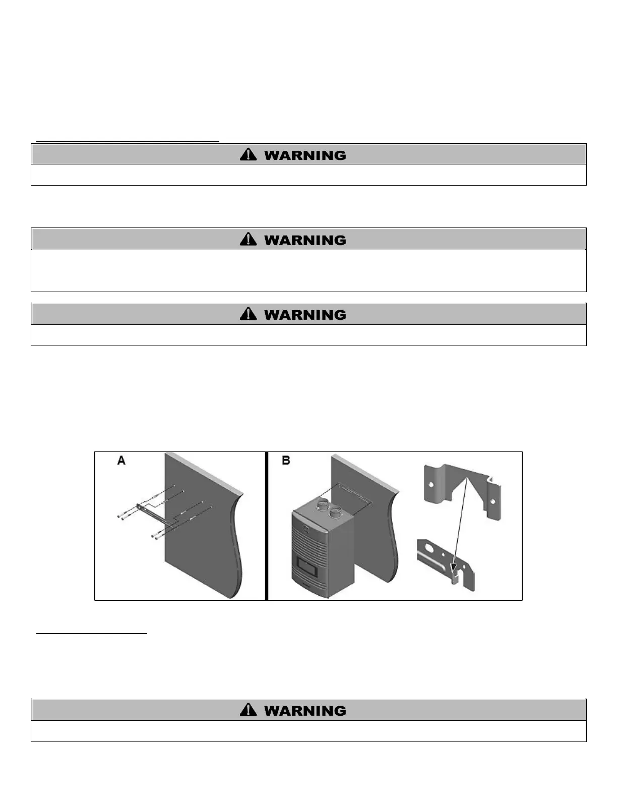
POSITIONING THE APPLIANCE ON THE WALL
1. Attach the wall bracket on the location where you want to install the appliance. Ensure it is level and on stud (16” centers)
before proceeding.
2. Mark the four drill holes with a pencil or marker. Remove the wall bracket.
3. Drill four (4) holes using a 5/32 drill bit at the marked hole locations.
4. Mount the wall bracket to the wall with the four (4) included anchor bolts. Ensure the mounted bracket is level. See Figure 6A.
5. Align the heater bracket grooves on the back of the appliance with the tongues on the wall bracket and hang the appliance on
the bracket. See Figure 6B.
Figure 6 – Wall Mounting the Appliance
K. FLOW RESTRICTOR
A flow restrictor is installed on this appliance at the DHW inlet adapter to avoid excessive flow at the faucets. See Flow Charts, this
manual, for more information.
If it is necessary to further increase flow to the system, replace the factory installed white flow restrictor with the blue included with the
appliance by following the instructions below.
If the appliance is already fully installed, turn the gas, power, and water off to the appliance and drain all water from the appliance
BEFORE proceeding. Failure to comply could result in substantial property damage, severe personal injury, or death.

 Loading...