14
LP-520 REV. 5.1.17
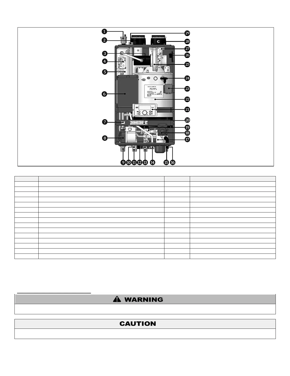
Figure 3 – Model Components
Condensate Air Pressure Switch
Manual ON/OFF Power Switch
Internal Recirculation Pump (DHW) / CH Internal Primary Pump
DHW Inlet Adapter With Filter and Flow Restrictor
Table 7 – Component List
PART 4 – PREPARE APPLIANCE LOCATION
A. UNCRATING THE APPLIANCE
UNCRATING APPLIANCE – Any claims for damage or shortage in shipment must be filed immediately against the transportation
company by the consignee.
Cold weather handling – If appliance has been stored in a very cold location (below 0
o
F) before installation, handle with care until the
plastic components come to room temperature.
Remove all sides of the shipping crate to allow the appliance to be lifted into its installation location.

 Loading...