28
LP-520 REV. 5.1.17
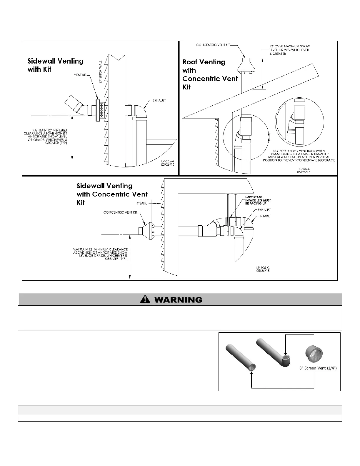
2. Direct Vent, Optional Horizontal and Vertical Vent Kits
Figure 14 – Direct Vent, Vent Terminations (With Optional Kits)
All vent pipes must be glued, properly supported, and the exhaust must be pitched a minimum of ¼” per foot back to the appliance to
allow drainage of condensate. When placing support brackets on vent piping, the first bracket must be within 1 foot of the appliance and
the balance at 4 foot intervals on the vent pipe. Appliance venting must be readily accessible for visual inspection for the first three feet
from the appliance.
3. Screen Installation
After connecting the intake air and exhaust vent pipes, it is required to install the
included screens into the exhaust vent and intake pipe terminations to prevent
damages to the unit due to blockages. Clean the vent terminations and cement
the screens into the terminations. See Figure 15 for installation detail.
Do not connect any other appliance vents to the appliance exhaust vent or intake pipes.
Figure 15 - Screen Installation

 Loading...