LTE CPE B2368 User's
Guide 13 L2TP VPN
Issue 01 Copyright © Huawei Technologies Co., Ltd. 97
Item Description
Restore Click this button to update the screen.
4.13 Configuration Example L2TP VPN tunnel Layer 3
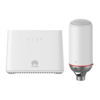
This is a diagram of a network structure in the example below:
Figure 13-4 Example of a network structure of the L2TP tunnel to the VPN Layer 3 Figure 13-4 Example of a network structure of the L2TP tunnel to the VPN Layer 3
A CPE WAN IP is 172.23.40.48, which is to the LAN connected to a computer with an IP address
192.168.1.51. L2TP server uses WAN IP 172.23.40.25 and is effected within a LAN connected computer with an IP
address of 192.168.2.2. IP address of the computer on the LAN must come from a different domain subnet. L2TP VPN
tunnel layer 3 can be set using the web configuration interface.
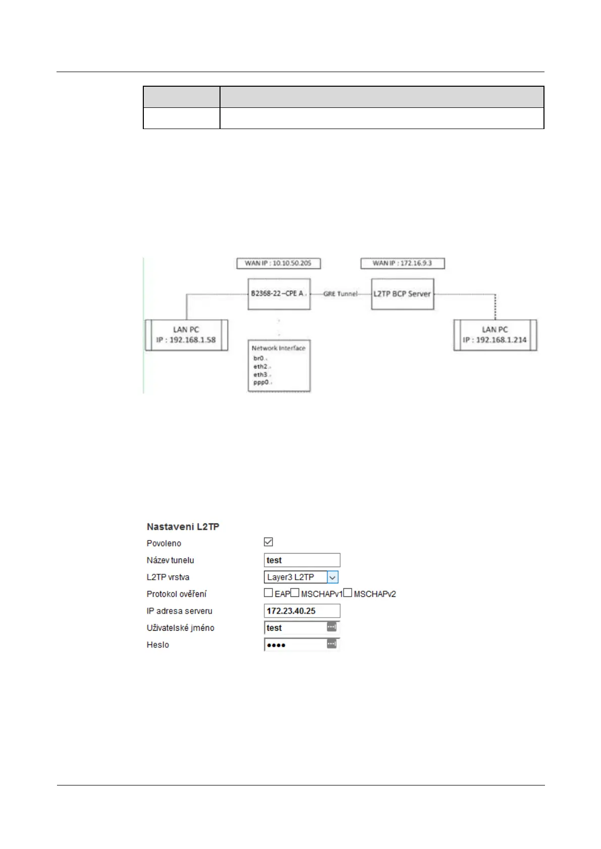
Figure 13-5 Example configuration L2TP VPN tunnel Layer 3 Add a new tunnel Figure 13-5 Example configuration L2TP VPN tunnel Layer 3 Add a new tunnel
Both CPE activated ppp0 interface and L2TP server assigns L2TP CPE and IP address (192.168.3.2). After
creating the L2TP VPN tunnel layer 3 is also a need to create a static routing rule (click Add new static creating the L2TP VPN tunnel layer 3 is also a need to create a static routing rule (click Add new static
routing on the screen Network Settings> Static Routing, or on the icon adjust on the right side of the table). routing on the screen Network Settings> Static Routing, or on the icon adjust on the right side of the table). routing on the screen Network Settings> Static Routing, or on the icon adjust on the right side of the table). routing on the screen Network Settings> Static Routing, or on the icon adjust on the right side of the table). routing on the screen Network Settings> Static Routing, or on the icon adjust on the right side of the table). routing on the screen Network Settings> Static Routing, or on the icon adjust on the right side of the table).
By default, the CPE does not send any data flow through the L2TP tunnel. IN
 Loading...