Figures
Figure 2-1 Customized alarms collected by the UPEU or UEIU.........................................................................2-3
Figure 2-2 Customized alarms collected by the EMUA (1).................................................................................2-4
Figure 2-3 Customized alarms collected by the EMUA (2).................................................................................2-4
Figure 2-4 Slot assignment for the UPEU and UEIU.......................................................................................... 2-5
Figure 2-5 Monitoring principles of the DBS3900 when the BBU is installed in the APM30............................2-6
Figure 2-6 Monitoring principles of the DBS3900 when the BBU is installed in the APM30H (Ver.A)...........2-7
Figure 2-7 Monitoring principles of the DBS3900 when the BBU is installed in the APM30H (Ver.B)........... 2-7
Figure 2-8 Monitoring principles of the DBS3900 when the BBU is installed in the APM30H (Ver.B)........... 2-8
Figure 2-9 Monitoring principles of the DBS3900 when the RRU is powered and monitored by the APM30H
(Ver.B)...................................................................................................................................................................2-8
Figure 2-10 Monitoring principles of the DBS3900 when the BBU is installed in the OMB.............................2-8
Figure 2-11 Monitoring principles of the DBS3900 in the BBU+RRU+ICR (110V/220V) scenario.................2-9
Figure 2-12 Monitoring principles of the DBS3900 in the BBU+RRU+IMB03 (110V/220V) scenario............2-9
Figure 2-13 Monitoring principles of the DBS3900 when the BBU is installed in the TMC or TMC11H.........2-9
Figure 2-14 Monitoring principles of the DBS3900 when the BBU is installed in the OMB...........................2-10
Figure 2-15 Monitoring principles of the DBS3900 when the BBU is installed in the APM30H (Ver.B) in the +24
DC power supply scenario..................................................................................................................................2-10
Figure 2-16 Monitoring principles of the DBS3900 in the BBU+RRU+ICR (+24 V DC) scenario.................2-10
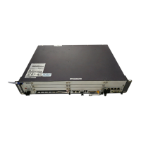
Figure 3-1 BBU3900............................................................................................................................................3-2
Figure 3-2 The position of the ESN..................................................................................................................... 3-2
Figure 3-3 Slots of the BBU3900.........................................................................................................................3-3
Figure 3-4 BBU3900 in typical configuration..................................................................................................... 3-5
Figure 3-5 Panel of the WMPT............................................................................................................................3-6
Figure 3-6 LEDs besides the three ports on the WMPT...................................................................................... 3-7
Figure 3-7 DIP switches on the WMPT...............................................................................................................3-9
Figure 3-8 Panel of the WBBPa.........................................................................................................................3-10
Figure 3-9 Panel of the WBBPb.........................................................................................................................3-10
Figure 3-10 Panel of the WBBPd.......................................................................................................................3-10
Figure 3-11 Panel of the FAN unit.....................................................................................................................3-13
Figure 3-12 Panel of the UPEUA.......................................................................................................................3-14
Figure 3-13 Panel of the UPEUB.......................................................................................................................3-15
Figure 3-14 Slots in the BBU.............................................................................................................................3-15
Figure 3-15 Panel of the UEIU...........................................................................................................................3-16
Figure 3-16 Panel of the UTRP2 supporting two optical ports..........................................................................3-18
BBU3900
Hardware Description Figures
Issue 11 (2010-11-10) Huawei Proprietary and Confidential
Copyright © Huawei Technologies Co., Ltd.
ix
 Loading...

