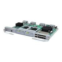
Figure 3-17 Panel of the UTRP3 and UTRP4 supporting eight E1s/T1s...........................................................3-18
Figure 3-18 Panel of the UTRP6 supporting one STM-1 .................................................................................3-18
Figure 3-19 Panel of the UTRP supporting four electrical ports........................................................................3-18
Figure 3-20 DIP switch on the UTRP3 or UTRP4.............................................................................................3-21
Figure 3-21 Panel of the USCUb1 (0.5 U).........................................................................................................3-23
Figure 3-22 Panel of the USCUb2 (1 U)............................................................................................................3-23
Figure 4-1 PGND cable........................................................................................................................................4-5
Figure 4-2 BBU power cable (1)..........................................................................................................................4-6
Figure 4-3 BBU power cable (2)..........................................................................................................................4-6
Figure 4-4 Appearance of power cable(AC OMB)..............................................................................................4-7
Figure 4-5 Appearance of power cable(DC OMB)..............................................................................................4-8
Figure 4-6 E1/T1 cable.........................................................................................................................................4-8
Figure 4-7 E1/T1 surge protection transfer cable...............................................................................................4-11
Figure 4-8 FE/GE cable......................................................................................................................................4-12
Figure 4-9 FE/GE surge protection transfer cable..............................................................................................4-13
Figure 4-10 FE/GE optical cable (FC and LC connectors)................................................................................4-14
Figure 4-11 FE/GE optical cable (SC and LC connectors)................................................................................4-14
Figure 4-12 FE/GE optical cable (LC and LC connectors)................................................................................4-14
Figure 4-13 Multi-mode optical cable ...............................................................................................................4-15
Figure 4-14 The connections of the multi-mode CPRI optical fiber..................................................................4-15
Figure 4-15 Single-mode optical cable..............................................................................................................4-16
Figure 4-16 The connections of the single-mode CPRI optical fiber.................................................................4-16
Figure 4-17 Monitoring signal cable between the APMI and the BBU.............................................................4-18
Figure 4-18 Monitoring signal cable for the transmission cabinet.....................................................................4-19
Figure 4-19 Monitoring signal cable between the HEUA and the BBU............................................................4-20
Figure 4-20 EMUA monitoring signal cable......................................................................................................4-21
Figure 4-21 Monitoring signal cable between the CMUA and the BBU...........................................................4-22
Figure 4-22 BBU alarm cable............................................................................................................................4-23
Figure 4-23 GPS clock signal cable...................................................................................................................4-24
Figure 5-1 10 U indoor centralized rack...............................................................................................................5-3
Figure 5-2 OMB cabinet.......................................................................................................................................5-5
Figure 5-3 IMB03.................................................................................................................................................5-6
Figure 5-4 DC IMB03..........................................................................................................................................5-7
Figure 5-5 AC IMB03..........................................................................................................................................5-8
Figure 5-6 DCDU-03............................................................................................................................................5-9
Figure 5-7 Ports on the panel of the DCDU-03..................................................................................................5-10
Figure 5-8 AC/DC power equipment.................................................................................................................5-11
Figure 5-9 DIP switches on the PMU................................................................................................................5-14
Figure 5-10 Exterior of the WGRU....................................................................................................................5-15
Figure 5-11 WGRU installed in the WGRU box...............................................................................................5-16
Figure 5-12 Front panel of the WGRU..............................................................................................................5-16
Figure 5-13 Rear panel of the WGRU box.........................................................................................................5-17
Figures
BBU3900
Hardware Description
x Huawei Proprietary and Confidential
Copyright © Huawei Technologies Co., Ltd.
Issue 11 (2010-11-10)
 Loading...

