SERIAL
SERIAL
SERIAL
SERIAL
ALMI2ALMI1
ALMO2
ALMO1
ALMO2
ALMO1
ALMO2
ALMO1
SERIAL
SERIAL
SERIAL
SERIAL
ALMI2ALMI1
ALMO2
ALMO1
ALMO1
ALMO2
ALMO1
ALMO2
ALMO1
ALMO2
ALMO1
34
6 Installing and Routing Alarm and Indicator Cables
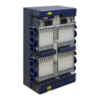
Installing and Routing External Alarm Cables
a
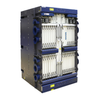
Installing and Routing Alarm Cables to Cabinet Indicators
b
The LAMP interfaces on the
EFI board provide 5 V power
for the indicators on a
cabinet. It cannot connect to
an RJ45 cable intended for
the NM_ETH, ETH, ALMO,
or CLK interface; otherwise,
the EFI board, the
connected test instrument,
or the equipment housing
the EFI board will be
damaged.
Cabinet indicator alarm
cable
Subrack 4
Subrack 3
Subrack 2
Subrack 1
To centralized alarm system
Subrack 8
Subrack 7
Subrack 6
Subrack 5
Black network cable
To the drive interface on the
cabinet top indicator
SERIAL
LAMP2
SERIAL
LAMP2
SERIAL
SERIAL
LAMP1
LAMP1
LAMP1
LAMP2
LAMP2
Subrack 4
Subrack 3
Subrack 2
Subrack 1
CAUTION

 Loading...