42
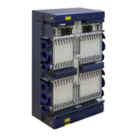
Installing the Digital Video O/E Conversion Chassis
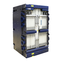
Appearance of the Digital Video O/E Conversion Chassis
a
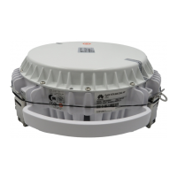
Appearance of the Power Supply Unit and Power Cable Connections
b
Installing and Routing Cables
e
Front
Rear
Installing and Routing Fibers
f
a
b
b
a
Route power cables and network cables along the left side of
the rack and insert them into corresponding ports.
b
Route electrical signal cables along the right side of the
rack and insert them into the corresponding ports.
c
When all cables need to be routed on the sides of the rack,
secure each cable to the rack at the specified bundling point on
the chassis.
a
b
a b
c c
a
Route fibers along the left side of the rack. If there are a large
number of fibers, you can route certain fibers along the right
side of the rack.
b
Insert fibers into the corresponding ports.
c
Wind fibers onto the winding pipe, and secure the winding
pipe to the rack at the specified bundling point on the
chassis.
c
Open the front door of the rack and then install fibers on
the front.
Open the rear door of the rack and then install cables on
the rear.
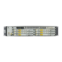
Rear view of a 19-inch rack
Front view of a 19-inch rack
Installing O/E Conversion Chassis
in 19 " Rack
d
Front
Rear
A B
AC input
(100-240 V)
Areas A and B each provide six power inputs for mutual backup. In areas A and B,
select a total of two power inputs (working and protection) that are identified with the
same number to provide power to the O/E conversion chassis.
AC input
(100-240 V)
O/E conversion
chassis
Power Consumption
c
Optical port
Electrical port
Other ports
Power port
Maximum Input Power 300 W
Maximum Output Power 250 W
DC Output Voltage 12 V
Rated Working Current 3.5 A
NOTE
NOTE

 Loading...