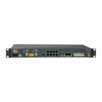
OptiX RTN 600
Product Description
Commercial in Confidence Page 25 of 44
OptiX RTN 600 OptiX RTN 600
1+1
E1/STM-1
1+1 1+1 1+1
OptiX RTN 600 OptiX RTN 600
Figure 5-3
Chain networking (with protection)
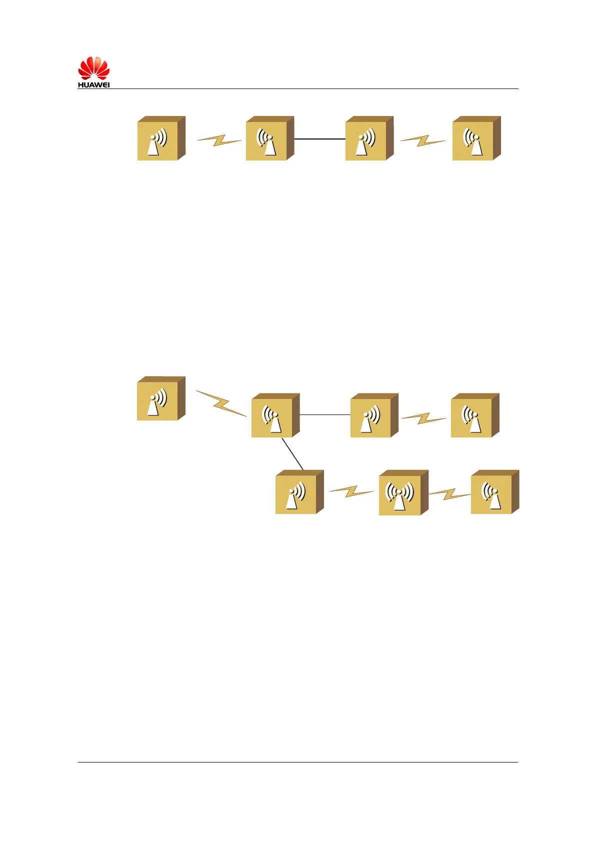
5.3 Tree Networking
In this networking mode, several chains are connected at one or more nodes, but the
nodes do not form a ring.
Figure 5-4 describes an application example of tree networking in a mobile network
backhaul transmission. For the nodes near the BSC side, the OptiX RTN 600 adopts
1+1 configuration and the microwave capacity is 16xE1 or 1xSTM-1. For the nodes at
the network edge, the OptiX RTN 600 adopts 1+0 configuration and the microwave
capacity is 4xE1.
OptiX RTN 600
8x E1
1+1
OptiX RTN 600
16 x E1/STM-1
OptiX RTN 600OptiX RTN 600
OptiX RTN 600
1+1
1+0
1+0
1+0
OptiX RTN 600
2+0
4 x E1
4x E1
1+0
OptiX RTN 600
Figure 5-4
Tree networking
5.4 Fiber Ring Networking
In this networking mode, optical transmission systems form a ring through fiber
connection, and microwave transmission systems are directly connected to the ring or
indirectly connected to the ring through STM-1o or STM-1e.
Figure 5-5 shows a network with a fiber ring and a microwave link directly connected
to the ring. In this example, the optical transmission systems and the OptiX RTN 600
systems form an STM-1 ring. The ring adopts the SNCP protection mechanism.
 Loading...