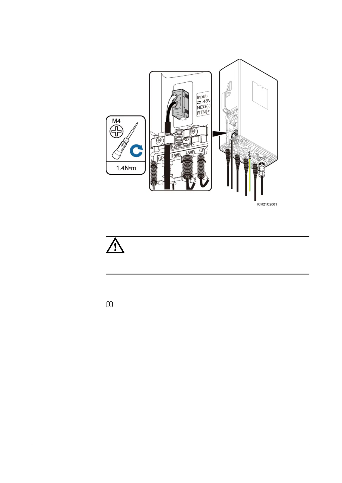
Figure 7-18 Installing an RRU power cable
CAUTION
Ensure that the exposed shield layer of the power cable is properly tightened using
the clip.
2. Connect the OT terminals of the blue and black/brown core wires at the other end of
the RRU power cable to the NEG(-) and RTN(+) wiring terminals of the LOAD0 on
the DCDU-03B respectively.
NOTE
One DCDU-03B can supply power to a maximum of six RRUs. The RRU power cable can be
connected to any wiring terminal from LOAD0 to LOAD5 on the DCDU-03B.
3. Lay out the cable by referring to 7.1 Cabling Requirements, and then bind the cable
using cable ties.
4. Label the installed cable by referring to Attaching a Cable-Tying Label.
l Install an RRU power cable that feeds power to an RRU from the embedded power system
(EPS) when the EPS is configured.
1. Link the easy power receptacle (pressfit type) connector at one end of the RRU power
cable to the power supply socket on the RRU, as shown in Figure 7-18.
2. Link the easy power receptacle (pressfit type) connector at one end of the RRU power
cable to the RRU0 port on the EPS subrack.
RRU3232
Installation Guide 7 Installing RRU Cables
Issue 05 (2011-10-20) Huawei Proprietary and Confidential
Copyright © Huawei Technologies Co., Ltd.
75
 Loading...