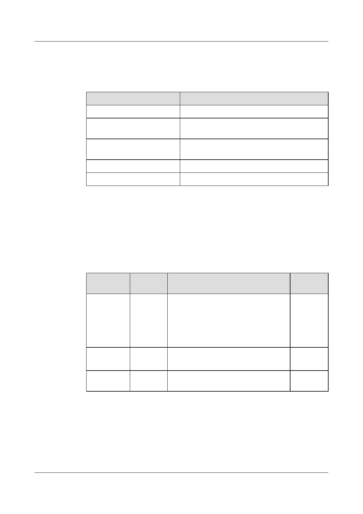
Table 7-5 shows the mapping between the output tributary switches and the load tributaries.
Table 7-5 Mapping between the output tributary switches and the load tributaries
Output Tributary Switch Load Tributary
BATT. BATT.(-) (two channels) and BATT.(+) (two channels)
LOAD1 LOAD1(-) (two channels) and LOAD1(+) (two
channels)
LOAD2 LOAD2(-) (two channels) and LOAD2(+) (two
channels)
LOAD3 LOAD3(-), LOAD3(+)
LOAD4 LOAD4(-), LOAD4(+)
DIP Switch
The EPS75-4815AF power system provides a DIP switch, the DIP switch is on the right middle
of the monitoring module control board, which can be seen after you remove the monitoring
module. The DIP switch has eight available electrical switches. ON indicates 1, and OFF
indicates 0. Table 7-6 describes the settings of DIP switch.
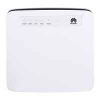
Table 7-6 Settings of the DIP switch
Electrical
Switch
Setting Indication Factory
Default
1-5 Supported Used to set the address of the environment
monitoring module.
1:OFF
2:OFF
3:OFF
4:OFF
5:OFF
6-7
Supported Used to set the rate of the serial port 6:ON
7:OFF
8 Not
supported
- OFF
The DIP switchs 1-5 are used to set the address of the environment monitoring module, Table
7-7 shows the settings of the Dip switchs.
UA5000 Universal Access Unit
Environment Monitoring 7 EPS75-4815AF Monitoring Solution
Issue 01 (2012-08-17) Huawei Proprietary and Confidential
Copyright © Huawei Technologies Co., Ltd.
87