5
Wireless Rain-Clik Components
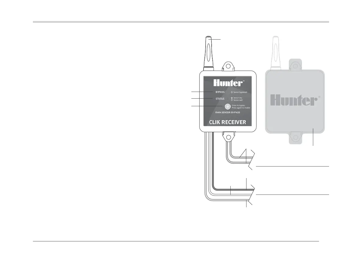
Wireless Receiver
1. Bypass Button: Allows automatic or manual watering
when the sensor is active.
2. Receiver Status LED: Used to indicate the status of
the sensor.
3. Receiver Bypass LED: Indicates when sensor has
been bypassed.
4. Radio Antenna: Receives a wireless signal from the
transmitter up to 800' (243 m) line-of-sight. The
antenna should be oriented vertically.
5. AC Power Wires: The two yellow wires are attached to
a 24 VAC source from the controller.
6. Receiver Wires: The sensor wires are attached to either
the sensor terminals in the controller or in-line with the
valve common wire.
• Blue/White Wires: Used for normally closed sensor
applications (Hunter controllers).
• Blue/Orange Wires: Used for normally open sensor
applications.
7. Rubber Cover: Used to protect the receiver when
mounted in outdoor locations.
Yellow to 24 VAC power
Blue/orange wires to
normally open sensor
terminals
Blue/white wires
to normally closed
sensor terminals
Yellow
Blue
White
Orange

 Loading...


