Wireless
Rain Sensor
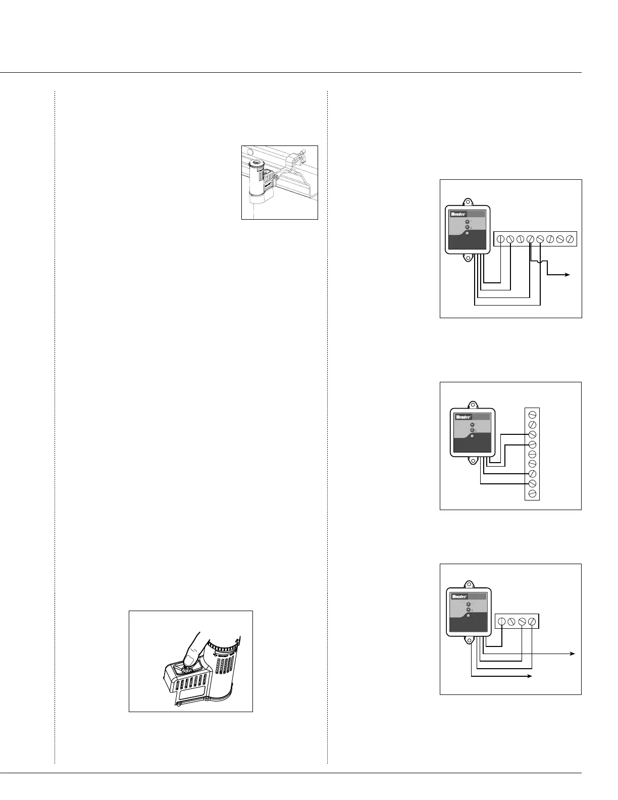
Hunter SRC
R RS C 1ACAC 2 3
W
B
Y
Y
Common Wire
to all Valves
Red light indicates
sensor is bypassed
GREEN = Sensor is dry
RED = Sensor is wet
SENSOR BYPASS
SENSOR STATUS
WIRELES S
RAIN
SENSO R
RAIN SENSOR BYPASS
Press to bypass, press
again to re-enabl
e
Fig. 2
Wireless
Rain Sensor
Hunter ICC/Pro-C/EC
SEN
SEN
C
TEST
P MV
AC
AC
G
REM
Red light indicates
sensor is bypassed
GREEN = Sensor is dry
RED = Sensor is wet
SENSOR BYPASS
SENSOR STATUS
WIRELES S
RAIN
SENSO R
RAIN SENSOR BYPASS
Press to bypass, press
again to re-enabl
e
B
W
Y
Y
Fig. 3
Other
Controllers
P MVC
Wireless
Rain Sensor
AC AC
W
B
Y
Y
O
Common Wire
to all Valves
Red light indicates
sensor is bypassed
GREEN = Sensor is dry
RED = Sensor is wet
SENSOR BYPASS
SENSOR STATUS
WIRELES S
RAIN
SENSO R
RAIN SENSOR BYPASS
Press to bypass, press
again to re-enabl
e
Used for normally
open sensor
applications
Fig. 4
11
and standard mount supplied with the
Wireless Rain-Clik™, and reinstall
the gutter mount. Position the gutter
mount on the edge of the gutter and
twist the thumbscrew to secure it
in place.
Helpful Hints for Mounting:
A. Choose a location such as on the side of a building
or post. The closer the Wireless Rain-Clik is to the
controller, the better reception will be. DO NOT
EXCEED 300 feet.
B. Correct placement of the Wireless Rain/Freeze-Clik
model is important for accurate temperature sensing.
The best location would be out of direct sunlight.
C. As described in the “Operation” section of this man
-
ual, “reset rate” refers to the amount of time it takes
the Wireless Rain-Clik to dry out suficiently for the
sprinkler system to be allowed to come back on. The
mounting location will affect this rate and should be
taken into consideration should extreme conditions
exist. For example, mounting the Wireless Rain-Clik
on a very sunny, southern end of a building may
cause the Wireless Rain-Clik to dry out sooner than
desired. Similarly, mounting on the northern end
of a building with constant shade may keep the
Wireless Rain-Clik from drying soon enough.
Transmitters/Sensor
• Nothing to set up with this unit after installation
• The unit can be tested stand-alone as follows: press
and hold the post on the quick response section
(See Fig. 1). Within 3 seconds of pressing and hold-
ing this post down, the LED protruding from the
potting should blink once. Release the post, within
3 seconds the LED should blink once again.
Manually depress the spindle at
the top of the Wireless Rain-Clik
Fig. 1
Wiring To Your Irrigation System
Receiver Installation, SRC Controller: (See Fig. 2)
1. Attach the two
yellow wires to
the AC termi-
nals of the SRC
(polarity does not
matter).
2. Attach the blue
wire to the RS
terminal.
3. Attach the white
wire to the “C”
terminal.
4. Attach the valve common wire to the RS terminal.
Receiver Installation EC, Pro-C and ICC Controllers:
(See Fig. 3)
1. Attach the two
yellow wires to
the AC terminals
of the controller
(polarity does not
matter).
2. Attach the blue
wire to one SEN
terminal and the
white wire to the
other SEN terminal of the controller.
Receiver Installation, Other Controllers:
A. Normally Closed Sensor Applications (See Fig. 4)
1. Attach the two
yellow wires to
the AC terminals
of the controllers
(polarity does not
matter).
2. To attach the
receiver to this
type of control-
ler, attach the
blue wire and the
white wire to the sensor terminals of the controller,
or in-line with the valve common.
Wireless Rain-Clik
™
Sensor

 Loading...


