35
Models
Operating Specifications
Temperature: 0 to 150 degrees F
Pressures: up to 200 PSI
Humidity: up to 100%
Additional Features
Programmable Start Up Delay (0 to 300 seconds)
Programmable Interrupt Period (2 to 60 minutes)
System Status Indicator Light
One Button System Calibration
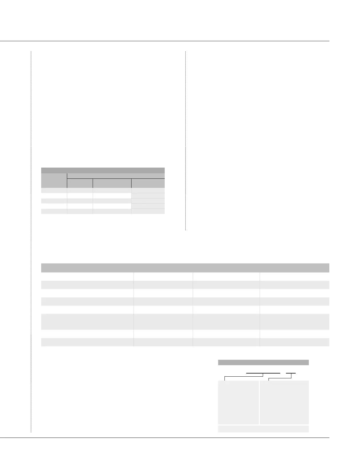
FLOW RANGE
Flow Sensor
Diameter
Operating Range (GPM)
Minimum* Suggested Maximum** Maximum (for sensor)
1" 6 17 50
1½" 13 35 100
2" 20 55 200
3" 40 120 300
4" 60 200 400
* Minimum recommended flow for the highest flow zone for your system
** Good design practice dictates the maximum flow not to exceed 5ft/sec.
Suggested maximum flow is based upon Class 200 IPS plastic pipe
Electrical Specifications
Current Draw: (@ 24VAC) .025 amps
Switching Current: 2.0 amps
Maximum Distance between Interface Box and
Sensor = 1,000 ft.
Dimensions
Flow-Clik Interface Box (4.5"H x 5.5"W x 1.5"D)
Flow-Clik Sensor Body (FCT Series)
FCT 100 (4.8"H x 2.3"W x 4.5"L)
FCT 150 (5.4"H x 2.3"W x 4.6"L)
FCT 158 (5.4"H x 2.3"W x 5.1"L)
FCT 200 (5.9"H x 2.7"W x 4.7"L)
FCT 208 (6.0"H x 2.9"W x 5.4"L)
FCT 300 (7.0"H x 4.0"W x 6.2"L)
FCT 308 (7.0"H x 4.2"W x 6.4"L)
FCT 400 (6.5"H x 5"W x 6.5"L)
FEATURES Hunter
®
Flow-Clik™ Data Industrial 200 Series Rain Bird FS-P Series
Flow monitoring for less than $200 (1½" vavle)
√
Programmable startup delay
20-300 sec. up to 100 sec.
User adjustable set point
√ √
Programmable automatic controller reset
2-60 min. manual reset
Fast, easy hookup on any Hunter controller
√
Easily adaptable to other manufacterrs controllers
√
Needs separate relay control
(LARC) and relays
Separate transmitter,
power supply and software
Installation type
Male Threaded Tee
Saddle tee Glue-in Tee
Pressure: up to 150 PSI
√
Rain Bird
®
is a registered trademark of Rain Bird Sprinkler Manufacturing Corporation
Data Industrial
®
is a registered trademark of Data Industrial Corporation
FLOW SENSOR PRODUCT COMPARISON
S P E C I F I C A T I O N G U I D E
EXAMPLE: FLOW-CLIK - 150
MODEL
FLOW-CLIK = Standard Ver-
sion for all 24VAC Controllers
(includes sensor and
interface panel)
FLOW-CLIK IMMS
= Version
for use with IMMS™
Central Control (includes
sensor only - interface panel
not required for IMMS™
)
FEATURES
100 = 1" Schedule 40 Sensor Body
15
0 = 1½" Schedule 40 Sensor Body
15
8 = 1½" Schedule 80 Sensor Body
20
0 = 2" Schedule 40 Sensor Body
208 = 2" Schedule 80 Sensor Body
300 = 3" Schedule 40 Sensor Body
308 = 3" Schedule 80 Sensor Body
400 = 4" Schedule 40 Sensor Body
NOTE = Order Flow-Clik Sensor Bodies Separately (FCT series)
SPECIFICATIONS
Flow-Clik
™
Sensor

 Loading...


