8
Mounting
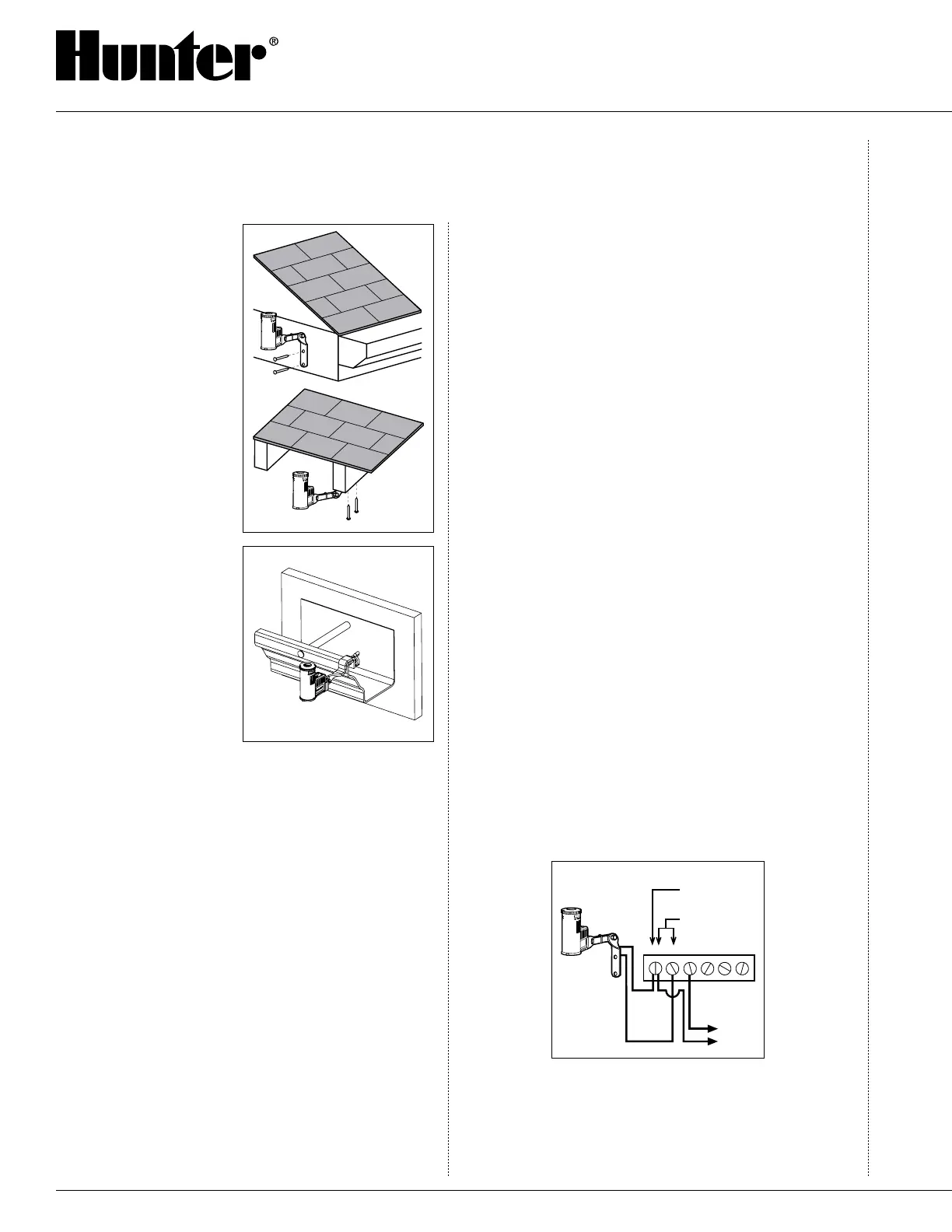
Standard Mount: Us-
ing the screws provided,
mount the Rain-Clik™
on any surface where it
will be exposed to unob-
structed rainfall, but not
in the path of sprinkler
spray. The switch-housing
portion must be upright,
but the swivel-bracket can
be moved for mounting on
any angled surface.
Gutter Mount: (SGM Sold
Separately): The gutter
mount can be purchased
as an optional accessory
for your Rain-Clik (order
p/n SGM). The SGM al-
lows the Rain-Clik to be
mounted directly to the
side of a gutter. To install
your Rain-Clik on a gutter,
Remove the screw, nut and
standard mount supplied
with the Rain-Clik, and
reinstall the gutter mount. Position the gutter mount
on the edge of the gutter and twist the thumbscrew to
secure it in place.
Helpful Hints for Mounting:
A. When looking for a suitable location such as on the
side of a building or post, the closer the Rain-Clik
is to the controller, the shorter the wire run will be.
This will also minimize the chance for wire breaks.
B. The ideal location for mounting is not always the
most practical location. In the case where a compro-
mise must exist (such as low location on a side wall
rather than the preferred high location), note that the
Rain-Clik will still work as it will always receive
some rainfall–it just will not be as accurate in its
gauging as it could be.
C. As described in the “Operation” section of this man
-
ual, “reset rate” refers to the amount of time it takes
the Rain-Clik to dry out sufficiently for the sprinkler
system to be allowed to come back on. The mount
-
ing location will affect this rate and should be taken
into consideration should extreme conditions exist.
For example, mounting the Rain-Clik on a very
sunny, southern end of a building may cause the
Rain-Clik to dry out sooner than desired. Similarly,
mounting on the northern end of a building with
constant shade may keep the Rain-Clik from drying
soon enough.
Once the Rain-Clik is mounted, run the wire to the
controller, and fasten it every few feet with wire clips
or staples for best results. If an extension to the wire
provided is needed, use the following table to deter-
mine the minimum wire gauge needed:
If the extension needed is:
25-50 feet use: 20 gauge
50-100 feet use: 18 gauge
100 feet or more use: 16 gauge
Wiring To Your Irrigation System
For the Rain-Clik: WARNING! This unit is designed to
be installed in conjunction with 24VAC circuits only.
Do not use with 110 or 220VAC circuits. All wiring
must conform to National Electrical Code or applicable
local codes.
Wiring to the Hunter SRC
The Rain-Clik connects directly to the SRC. This
allows you to easily override the sensor by using the
RUN (BYPASS SENSOR) position on the dial.
1. Route the wires from the Rain-Clik up through the
same opening used for valve wiring.
2. Connect one wire to the RS terminal and other to
the C terminal (See Fig. 1).
1 2 3 4
Rain-Clik
Hunter SRC
C
Fig. 1
RS
Connect Common to
this Terminal when
using Rain Sensor
Connect Rain
Sensor Wires to
These Two Te
rminals
Solenoid
Va
lves
3. Connect the valve common to the RS terminal.
INSTALLATION AND MAINTENANCE

 Loading...


