9
Wiring to the Hunter EC, Pro-C or ICC
The Rain-Clik connects directly to the EC, Pro-C
and ICC.
1. Remove the jumper from the two “SEN” terminals.
2. Route the wires from the rain sensor up through the
same conduit opening used for valve wiring.
3. Connect one wire to the terminal labeled “SEN”
and the other wire to the other “SEN” terminal
(See Fig. 2).
Rain-Clik
Hunter ICC/Pro-C
SEN
SEN
C
TEST
P MV
Fig. 2
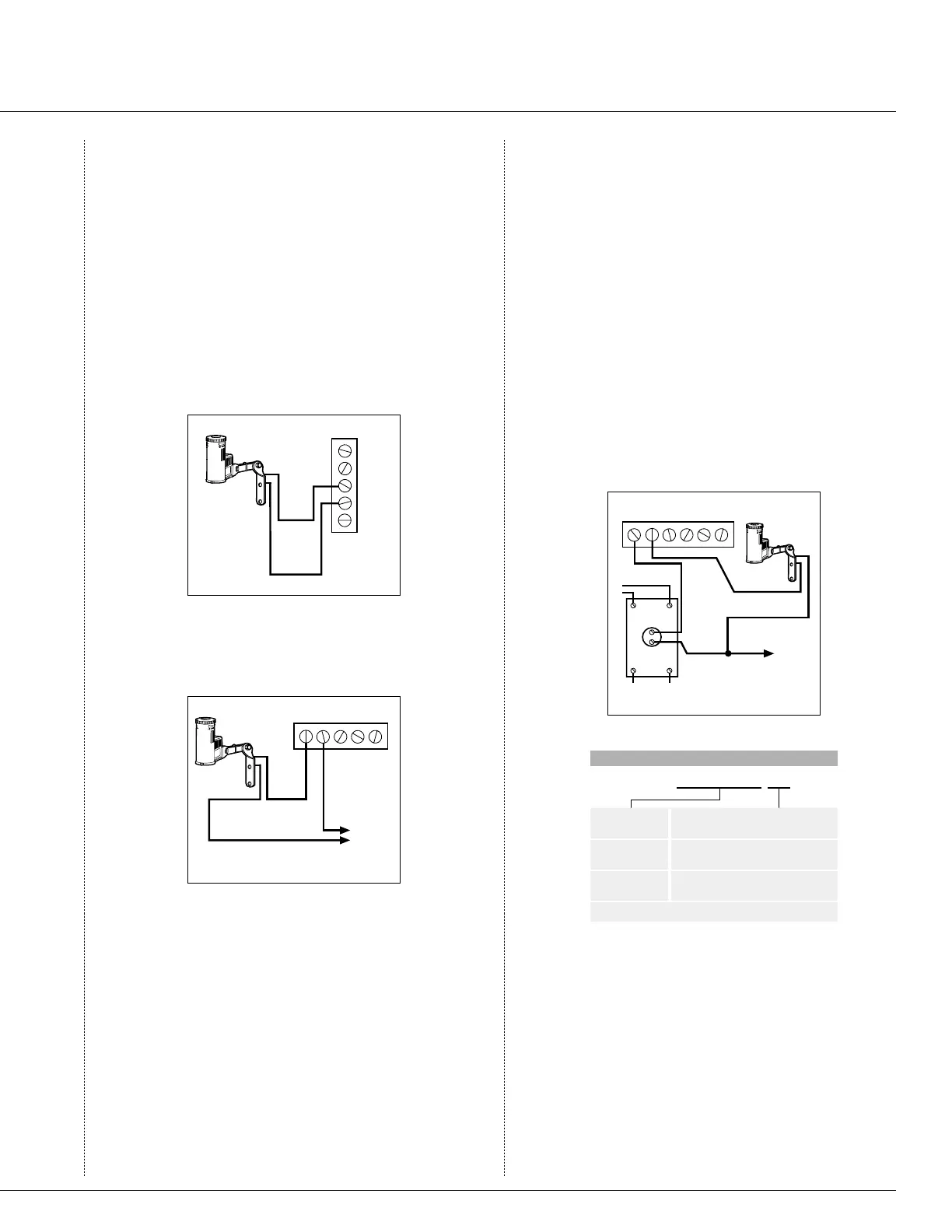
Other Controllers
The two most common situations are shown below.
A. 24 Volt Solenoid Valves Only (No booster pump)
(See Fig. 3).
1 2 3 4
Rain-Clik
Controller
C
Solenoid
Valves
Common Wire to
All Valves
Fig. 3
With the two wires from the Rain-Clik™ at the
controller, locate the “common ground” wire of the
solenoid valves. If it is connected to the common
terminal on the controller, disconnect it. Attach one
wire of the Rain-Clik to the “common” terminal
(usually marked “C”) on the controller. Attach the
other wire of the Rain-Clik to the common wire
leading to the valves. Note: The common wire to
the valves does not have to be interrupted at the
controller. The Rain-Clik may be wired anywhere
along the common wire line.
B. 24 Volt Solenoid Valves with Booster Pump
(See Fig. 4).
Locate the common wire to the solenoid valves and
the common wire leading to the coil of the relay that
starts the pump. If these two wires are connected to
the “common” terminal on the controller, discon-
nect both of them.
Twist together these two wires along with one wire
from the Rain-Clik, and secure with a wire nut.
Attach the other wire of the Rain-Clik to the “com-
mon” terminal on the controller. Note: The pump
circuit output must be 24 Volts in this situation. Do
not proceed if 110V.
Normally-
Open Rela
y
1 2 3 4
Controller
C
Solenoid
Valves
Common
Wire to Al
l
Valves
Rain-Clik
Pump
or MV
Line-In
Line-Out (to Pump)
Fig. 4
S P E C I F I C A T I O N G U I D E
EXAMPLE: RAIN-CLIK-NO
MODELS
RAIN-CLIK*
OPTIONS
NO = Normally Open Switch
WRC=WIRELESS
RAIN-CLIK
INT = Europe/Australia and other markets
(433 mHz Operating Frequency)
WRFC=WIRELESS
RAIN/FREEZE-CLIK
*Note: The Standard Model is a normally closed version.
Rain-Clik
™
Sensor

 Loading...


