1 2 3 4
Freeze-Clik
®
Hunter SRC Controller
CRS
Connect Common to
this Terminal when
using Rain Sensor
Connect Rain
Sensor Wires to
These Two Terminals
Solenoid
Va
lves
Fig. 2
Freeze-Clik
®
Hunter ICC
Hunter Pr
o-C
Controller
SEN
SEN
C
TEST
P MV
Fig. 3
To Solenoid
Va
lves
Mini-Clik
®
Freeze-Clik
®
1 2 3 4
Controller
C
Common Wire
Fig. 5
1 2 3 4
Freeze-Clik
®
Controller
C
Common Wire to
All Va
lves
To Solenoid
Va
lves
Fig. 4
22
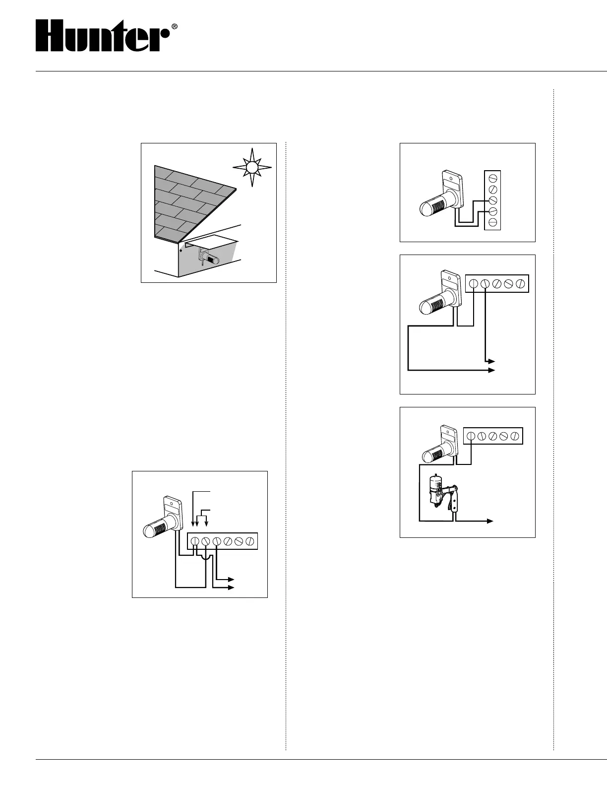
If the best location
for temperature sens-
ing is not a feasible
location for mounting
the Freeze-Clik
®
, an al-
ternate location may be
chosen if, in addition,
a “sun guard” is used
(a piece of flashing, for
example) to shade the
Freeze-Clik during that
time of day that the sun
could hit it (see Fig. 1).
The Freeze-Clik housing is designed so that it
provides the sensing element some amount of shaded
protection from direct or indirect radiation, while al-
lowing air to move freely around it. Using the screws
provided, attach the Freeze-Clik to the chosen surface.
Run the extension wire to the controller.
Wiring
Wiring to the Hunter SRC Controller
The Freeze-Clik connects directly to the SRC. This
allows you to easily override the sensor by using the
RUN (BYPASS SENSOR) position on the dial.
1. Route the
wires from the
Freeze Clik up
through the same
opening used for
valve wiring.
2. Connect one wire
to the RS termi-
nal and other to
the C terminal
(See Fig. 2).
3. Connect the valve common to the RS terminal.
Wiring to the Hunter ICC, Pro-C and
EC Controller
The Freeze-Clik connects directly to the ICC, Pro-C
and EC. This allows you to easily override the sensor
by using the Sensor switch on the front panel.
1. Remove the jumper from the two “SEN” terminals.
2. Route the wires from the rain sensor up through the
same conduit opening used for valve wiring.
3. Connect one wire
to the terminal
labeled “SEN”
and the other
wire to the other
“SEN” terminal
(See Fig. 3).
Other Controllers
The Freeze-Clik
freeze sensor is wired
to the 24 VAC com-
mon ground circuit of
the solenoid valves
(as shown in Fig. 4).
Locate the common
ground wire of the
solenoid valves. If it
is connected to the
common terminal on
the controller, discon-
nect it.
Attach one lead of
the Freeze-Clik to the
common terminal on
the controller and the
other lead to the com-
mon ground wire of
the solenoid valves.
If a Mini-Clik
®
rain sensor is already
installed or is to be
part of the installation
(see Fig. 5), the freeze sensor is to be wired in series
with the rain sensor so that either (or both) devices can
control the circuit.
Operation
The Freeze-Clik is preset and is not adjustable. It will
break the common ground circuit, thereby keeping
the sprinkler system from operating at, or below, 3˚C
(37˚F). At temperatures above 3˚C, it will close the
circuit for normal sprinkler operation.
Freeze-Clik-Rev Model: The temperature setting
works in reverse on this model with the circuit not
allowing operation of the sprinkler system above 3˚C
(37˚F). Once the temperature reaches this point or goes
below, it will activate the system and commence water-
INSTALLATION INSTRUCTIONS (continued)

 Loading...


