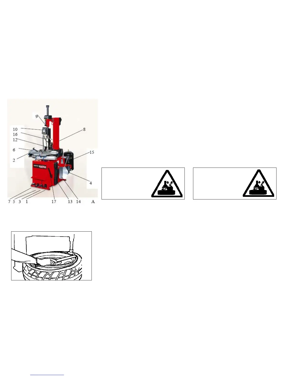
EasyManua.ls Logo

Hunter TCX550 - Page 30

Hunter TCX550
52 pages
To Next Page IconTo Next Page
To Previous Page IconTo Previous Page
Loading...
2
)
P
o
s
i
z
i
o
n
a
r
e
m
a
nu
a
l
m
e
n
t
e
l
a
t
o
rr
e
tta
(
16,
F
i
g
.
A)
c
o
n
t
r
o
il
bor
do
del
cer
chio,
pr
emer
e
il
pulsante
giallo
situato
sulla
ma
-
niglia
(
9,
Fig.
A)
che
pr
ovoca
il
bloccaggio
contemporaneo
dell'asta
esagonale
(
10,
Fig.
A)
e
del
braccio
orizzontale
(
11,
Fig.
A)
.
La
torr
etta
(
16,
Fig.
A)
verrà
automaticamente
alzata
e
allontanata di
2 mm.
dal bor
do del cer
chio.
3
)
C
o
n
l
'
a
i
u
t
o
d
e
ll
a
l
e
v
a
(
17,
F
i
g
.
A)
f
a
r
e
f
o
r
z
a
s
u
ll
'
app
o
gg
i
o
d
e
ll
a
torr
etta
(
16,
Fig.
A)
e
portar
e
il
tallone
del
pneumatico
sopra
la
parte a for
ma di unghia della torr
etta stessa.
N.B.
:
Per
evitar
e
di
pizzicar
e
la
camera
d'aria
è
consigliabile
ef
fettuar
e
questa operazione
con
la
valvola
a
cir
ca
10
cm
.
a
destra della torr
etta.
M
a
n
t
e
n
e
n
d
o
l
a
l
e
v
a
i
n
q
u
e
s
ta
p
o
s
i
z
i
o
n
e
f
a
r
e
r
u
o
ta
r
e
l
'
a
u
t
o
c
e
n
-
trante
(
2,
Fig.
A)
in
senso
orario
tenendo
pr
emuto
il
pedale
(
1,
Fig.
A)
no
a
che
il
pneumatico
non
sia
uscito
completamente
dal cer
chione.
2
)
P
o
s
i
t
i
o
n
t
h
e
m
o
un
t
/
d
e
m
o
un
t
t
oo
l
(
16,
F
i
g
.
A)
b
y
h
a
n
d
a
g
a
i
n
s
t
the
edge
of
the
rim.
Pr
ess
the
yellow
button
on
the
handle
(
9,
Fig. A
). The
vertical slide (
10,
Fig. A
) and swing arm (
11,
Fig. A
)
will
be
automatically
locked
in
position
and,
at
the
same
time,
the
mount/demount
head
(
16,
Fig.
A)
will
be
lifted
2
mm
of
f
the rim edge.
3)
W
ith
the
help
of
the
bead
lifting
tool
(
17,
Fig.
A)
inserted
over
the forwar
d end of the mount/demount tool
(
16,
Fig.
A)
and
below
the
top
bead,
lift
the
upper
bead
over
the knob portion of the mount/demount head.
N.B.
T
o
pr
event
pinching
the
inner
tube,
do
this
operation
with
t
h
e
v
a
l
v
e
ab
o
u
t
10
c
m
t
o
t
h
e
ri
g
h
t
o
f
t
h
e
m
o
un
t
/
d
e
m
o
un
t
tool.
Hold
the
bead
lifting
tool
in
this
position
and
hold
the
pedal
(
1,
Fig.
A)
depr
essed
to
tur
n
the
table
top
(
2,
Fig.
A)
clockwise
until the tyr
e comes completely of
f the rim.
T
ener
e le mani e le altr
e parti del
corpo il più lontano possibile dalla
torr
etta quando l'autocentrante è
in fase di r
otazione per evitar
e
rischi di schiacciamento.
T
o prevent industrial accidents,
keep hands and other parts of the
body as far fr
om the tool ar
m as
possible when the table top
is tur
nin
g
.
NOT
A:
Se
il
tallone
del
pneumatico,
in
gomme
partico
-
lar
mente
"dure",
tende
a
scender
e
dalla
torr
etta,
prima
d
i
r
u
o
t
a
r
e
l
'
a
ut
o
c
e
nt
r
a
nt
e
in
s
e
n
s
o
o
r
a
r
i
o
f
a
r
l
o
r
u
o
t
a
r
e
p
e
r
a
l
c
uni
c
e
nti
m
e
t
r
i
in
s
e
n
s
o
a
nti
o
r
a
r
i
o
,
m
a
nt
e
n
e
n
d
o
l
a
l
e
v
a
(17, Fig. A) in posizione come da
g. E.
4
)
Se il
p
neumatico ne é
p
r
ovvisto, to
g
lie
r
e la camera d'aria.
Note:
If
the
bead
rubber
is
particularly
har
d
and
stif
f,
it
will
tend
to
slip
of
f
the
mount/demount
tool.
T
o
pr
event
this,
befor
e
tur
ning
the
table
top
clockwise,
r
otate
it
an
-
ticlockwise
for
a
couple
of
centimeters
while
holding
the
bead lifting tool (17, Fig. A) as shown in Fig. E.
4)
Remove the inner tube if the tyre has one.
5)
P
r
oceder
e come
al punto 3 anche per il tallone inferio
r
e
6)
Pr
emer
e
il
pedale
(
7,
Fig.
A)
in
modo
che
il
palo
(
8,
Fig.
A
)
si
ribalti
in
posizione
di
fuori
lavor
o.
T
oglier
e
il
pneumatico
dal
cer
chio.
5)
Repeat
the
pr
ocedur
e
described
in
point
3
to
demount
the lower bead.
6)
Depr
ess
pedal
(
7,
Fig.
A
).
The
tower
(
8,
Fig.
A)
will
tilt
back
-
w
a
rd
s
t
o
i
t
s
n
o
n
-
w
o
r
k
i
n
g
p
o
s
i
t
i
o
n
.
R
e
m
o
v
e
t
h
e
t
y
r
e
f
r
o
m
t
h
e
rim.
30
E

Related product manuals