26 – English
E
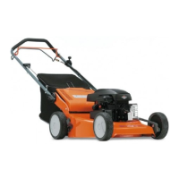
1. Engine
2. Engine stop function
3. Carburettor jet
4. Headlight
5. Cutting unit clutch
6. Battery 12 V, 20 Ah
C1.Capacitor 47µF, 150 V
F1. Fuse, 5 A
F2. Fuse, 15 A
G. Generator
K1. Relay
K2. Relay
K3. Starting relay
M. Starter motor
R1.Resistor
S1. Reset switch
S2. Changeover switch, manual/automatic
S3. Lights switch
S4. Switch, cutting unit
S5. Microswitch, grass collector full
S6. Microswitch, grass collector
S7. Microswitch underneath operator‘s seat
S8. Microswitch underneath clutch pedal
S9. Ignition switch
Ignition switched on
See fig. 3.
The circuit is made via L and B in the ignition switch
S9 and goes via the following components:
• Fuse F1.
• Lights switch S3.
• Operating coil in relay K2.
• Earthed via microswitch S7 underneath the
operator‘s seat.
When relay K2 is activated, the earthing connection
to the engine stop function in fig. 7 is broken, and
the starter motor function is earthed instead. Current
is supplied also via fuse F1 to the main jet 3 of the
carburettor, which is earthed to the engine.
fig. 3
ELECTRICAL SYSTEM
Eng-3 sidan 1-54 97-04-11, 15.3826
 Loading...