20
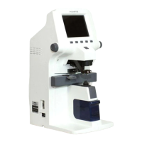
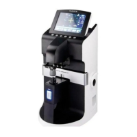
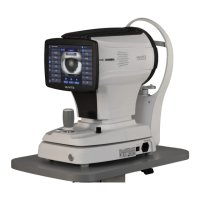
AUTO-LENSMETER
No
Component Removal method
1 Knob
2 Body rear cover
3 Cnnt bracket
4 RS 232c
5 Foot switch
6 On/Off switch
7
8
9
10
11
12
13
14
15
16
17
18
- First, separate 'Knob 1' from 'Knob pin 2' using M3 set
screw lench
- Next, separate 'Knob pin 2' unscrewing two M2.6X8L.
- Remove six screws at the back cover, and then separate
all screws at the bottom frame.
- Next, remove 4 round-head screws at 'Cnnt bracket' in
'Body rear cover' and separate the 'Cnnt bracket' from
'Body rear cover'. And then separate the 'Foot switch'
and the 'On/off switch'.
- Be careful that you never scratch on the surface of
'Cover' while assembling or disassembling.
- Assembly is the reverse procedure of disassembly
.

 Loading...