26
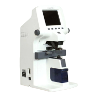
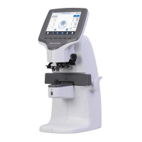
AUTO-LENSMETER
No
Component Removal method
1 PD assembly
2 PD shaft1
3 PD shaft2
4 PD main connect
5 Right PD connect
6 Left PD connect
7 PD guide cover
8 Ink case suppt
9 Ink case
10 Ink sponge
11 Ink cover(Lower)
12 Ink cover(Upper)
13
14
15
16
17
- We have to separate the 'PD assembly', the 'Ink assembly'
and the 'PD guide cover' from the body.
- Unscrew the 'PD shaft2,3' from the 'PD shaft(1).(2)' and
separate the 'PD main connector 4'.
- Pull to take out the 'PD shaft1' keeping the orientation
20deg clockwise rotated. And then, separate the 'PD shaft2',
the 'Connect 5,6', and the PD assembly.
- Remove the dish-head M2X6L screws and take out the
'PD guide cover'.
- Separate the 'Ink sub assembly' and the body and take
out the 'Ink case support 8' with unscrewing the M3X8L
screws.And then separate parts No 12, 11, 9 sequencially.
- Be careful to prevent from interfering with the 'Filter housing'
which is included in the optical components when
assembling or disassembling the PD assembly.
- Assembly is the reverse procedure of disassembly.

 Loading...