34
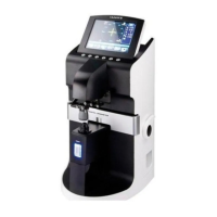
AUTO-LENSMETER
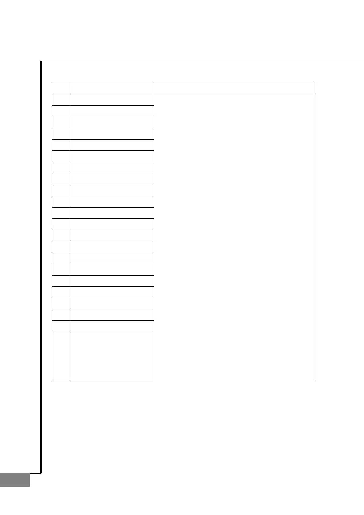
No
Component Removal method
1 Position suppt
2 Foot stopper(Upper)
3 Shaft suppt
4 Control position foot
5 Pen control suppt
6 Bush(D0406)
7 Position shaft
8 Position spring
9 E-ring(E2)
10 Washer
11 Fixing bracket spring
12 Fixing bracket
13 E-ring(E2)
14 Position foot spring
15 Position foot rubber sub ass'y
16 Pen guide shaft
17 Pen guide spring
18 E-ring(E2.5)
19 Pen control housing
20 Pen spring
21 Pen
22
- Separate 'Position support 1', 'Foot stopper 2',
'Shaft support 3', 'Control position foot 4' and
'Pen control support 5' sequencially.
- At 'Control position foot 4' and 'Pen control support 5',
remove the 'Bush 6', the 'Position shaft 7',
and 'Position spring 8' sequencially.
- Next, we have to disassemble locking parts at the
back of 'Position support'. Take out
'E-ring(2)', 'Washer 10', 'Spring 11', and
'Fixing bracket spring' in sequence.
- Next, we have to disassemble the 'foot rubber
sub ass'y' from the 'Control position foot'.
Remove the 'E-ring(2)', 'Spring 14', 'Spring 15' and
'Foot rubber sub ass'y' in order.
- Next, we have to disassemble the
'Pen control support 5' and the 'Pen control housing 20'.
Take out the 'Pen guide shaft 16' and remove the
'Pen guide spring 17'. Remove the 'E-ring 20',
'Pen spring 20', and 'Pen 21'.
- Assembly is the reverse procedure of disassembly.
.

 Loading...