46
AUTO-LENSMETER
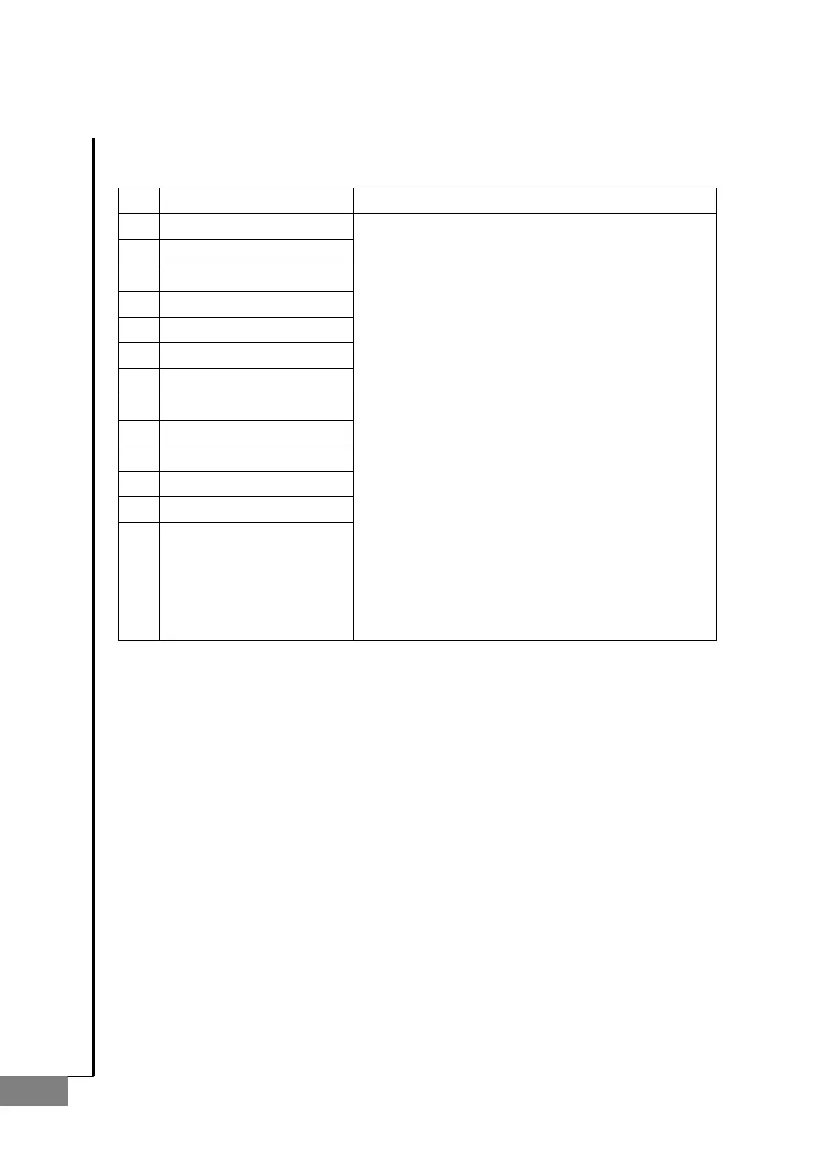
No
Component Removal method
1 Frame
2 Power supply ass'y
3 Power socket
4 Frame suppt(UV)
5 Power cover bracket
6 Foot rubber
7
8
9
10
11
12
13
- Separate the 'Power supply assembly' and the
'Frame' through removing four M3X6L screws.
- Remove the 'Power socket 3' through unscrewing
two M3X5L screws.
- Separate the 'Power cover bracket 5' and the
'Frame' and 'Frame support(UV) 4' through
removing four M3X5L screws.
- Separate the 'Frame support(UV) 4' and the 'Frame'
through removing four M3X5L screws.
- Finally, separate the 'Foot rubber 6' and the 'Frame'
through removing M3X10L screws.
- Assembly is the reverse procedure of disassembly.

 Loading...