SECTION 1
Electrical and Transducer Connections
The Miniflex LR has two-part screw terminals; the top part can be removed for ease of connection. It can be
powered from either an AC or DC supply.
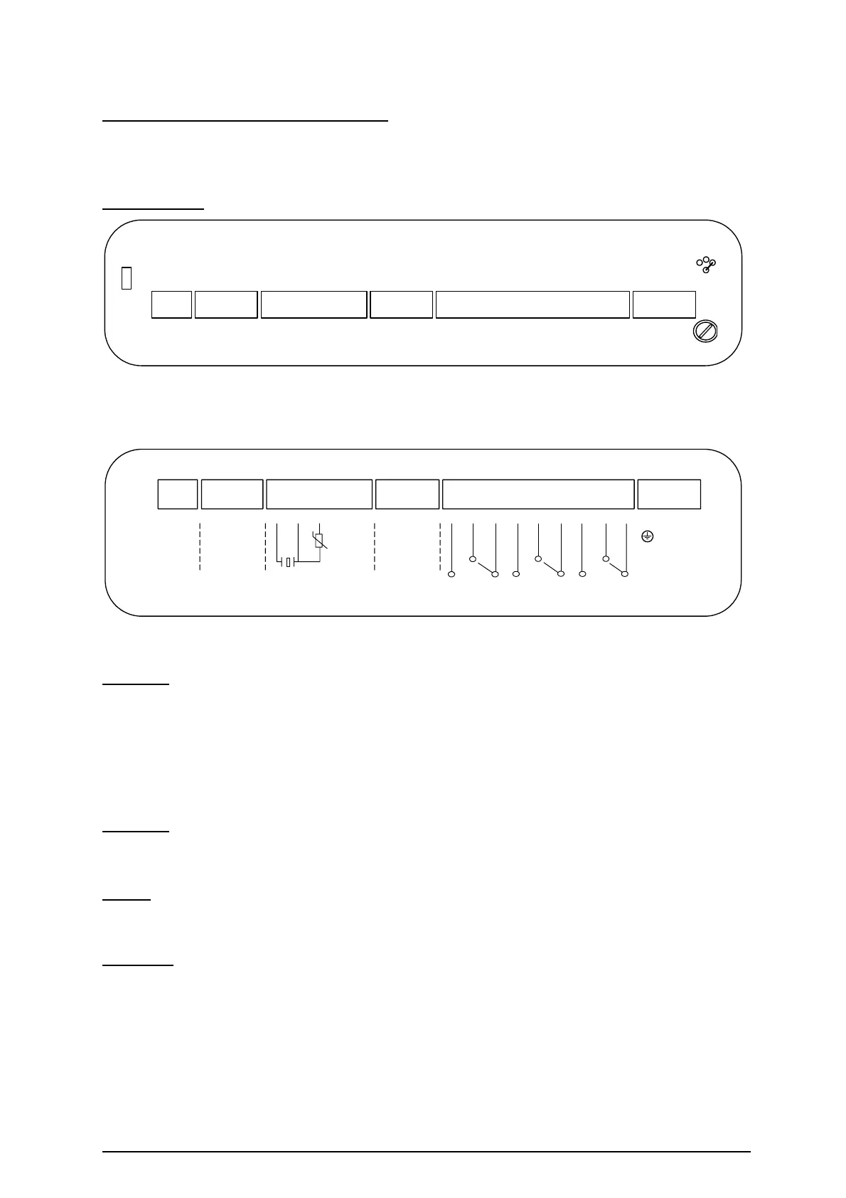
Power Supply Remove the terminal cover to expose the terminals shown below.
1 2 3 4 5 6 7 8 9 101112131415161718192021222324
25
TB1
TB2 TB3 TB4 TB5 TB6
F4
T250mA
95V
110V
230V
F3
T160mA
Figure 2: Terminals as seen in Miniflex LR.
The wiring instructions are on the inside of the terminal cover as shown below.
+
DC POWER
21.6-30VDC
9W
1
RELAY 1
RELAY 3RELAY 2
TRANSDUCER
SHIELD
E
L2
LN
-
SHIELD
+
ISOLATED
ANALOG
OUTPUT
SYNC
-
SHIELD
+
RS485
-
2 3 4 5 6 7 8 9 101112131415161718192021222324
25
L1
HOT
AC POWER
95/110/230V AC
+10%/-10%
50/60 HZ 12VA
Figure 3: Wiring diagram label inside MIniflex LR terminal cover
AC Supply The instrument will accept either 95V, 110V or 230VAC ±10%, 50Hz or 60Hz, 12VA.
A time lag fuse T160mA is fitted.
Select the voltage required using the jumper link situated just above terminal TB6.
Pass mains cable through cable gland and - Connect:- Earth to terminal 23
Neutral to terminal 24
Live to terminal 25
DC Supply The instrument will accept 21.6 - 30VDC, 5W. A time lag fuse T250mA is fitted.
- Connect :- Positive +ve to terminal 1
Negative -ve to terminal 2
Relays
3 SPDT Relays - rated at 8A/250VAC 8A/30V DC resistive, are connected at terminals 14 to 22, for activating
external alarms, contactors, pumps etc..
Transducer
Transducer RYV15 & RWV15 - is connected:- Black to terminal 6
Blue to terminal 7
Shield to terminal 9
Ref: MINIFLEX LR MANUAL Rev. 0 3