Pg 3.17
MITSUBISHI 100 INPUTS & OUTPUTSMITSUBISHI 100 INPUTS & OUTPUTS
MITSUBISHI 100 INPUTS & OUTPUTSMITSUBISHI 100 INPUTS & OUTPUTS
MITSUBISHI 100 INPUTS & OUTPUTS
S/S
OV
X0
X2
X4
L
X5
X3
X1
24V
N
X10
X11
X12
X13
X6
X7
X14
X15
X16
X17
SG
A
Y0
Y1
Y2
Y3
Y4 Y6
Y5
Y7
COM3
COM2
Y10
Y11
Y12
Y13
COM4
Y14
Y15
Y16
Y17
COM1
D
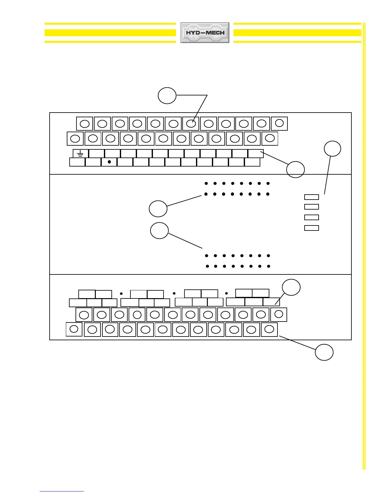
A - input terminals E - output indicating LED 's
B - input indicating LED's F - output terminal identification
C - input terminal identification G - PLC status indicator lights
D - output terminals
Input and output terminal identification : - the top row of identification labels corresponds
to the top row of terminals and the bottom row of labels to the bottom row of terminals.
Input and Output LED numbers correspond to the Input or Output of the same number.
ie. Input LED #0 corresponds to Input X0 . Output LED #0 corresponds to Output Y0
PLC Status indicators : Power - on when power exists to the PLC
Run - on when the PLC is running
Batt V - on when PLC memory backup battery has low voltage
condition
Prog E - on when PLC has a program error.
Power
Run
Batt V
Prog E
C
MITSUBISHI
F
IN
OUT
1
2
7
10
11
13
1514 1612
17
5
3
64
0
0
1
2
3
4
5
6
7
10
11
12
13
14
17
15
16
B
G
E
FX2N-32MR
 Loading...