EasyManua.ls Logo

Hyd-Mech M-16 User Manual

Hyd-Mech M-16
124 pages
To Next Page IconTo Next Page
Page #1 background imageLoading...
Page #1 background image
IN BANDSAW TECHNOLOGY
OPERATIONS &
MAINTENANCE
MANUAL
Question and Answer IconNeed help?

Do you have a question about the Hyd-Mech M-16 and is the answer not in the manual?

Hyd-Mech M-16 Specifications

General IconGeneral
BrandHyd-Mech
ModelM-16
CategorySaw
LanguageEnglish

Summary

Section I: Installation

Section 2: Operating Instructions

Section 2A: The Control Console

Start-Up

Procedure for safely starting the machine.

Manual Operation

Details on operating the machine in manual mode.

Section 2B: Saw Cutting Controls

Blade Basics

Fundamentals of blade selection and cutting.

Variable Speed Control

How to adjust the blade speed using the control.

Section 2C: Mechanical Controls

Coolant Flow

Information on adjusting and managing coolant flow.

Section 3: Maintenance and Troubleshooting

Lock-Out Procedure

Lock Out Procedure

Step-by-step procedure for implementing lockout/tagout.

Blade Changing

Blade Brush Adjustment

Blade Guides Adjustment

Lubrication

Hydraulic Maintenance

Cleanliness

Trouble Shooting

Saw is cutting out of square vertically

Troubleshooting steps for vertical square cutting issues.

Saw is cutting out of square horizontally

Troubleshooting steps for horizontal square cutting issues.

Blade comes off wheels

Troubleshooting steps for blade coming off the wheels.

Blade stalls in cut

Troubleshooting steps for blade stalling during a cut.

Blade vibrates excessively

Troubleshooting steps for excessive blade vibration.

Excessive blade breakage

Troubleshooting steps for frequent blade breakage.

Tooth strippage

Troubleshooting steps for tooth stripping issues.

No Coolant Flow

Saw Will Not Start

Saw Starts But Will Not Run After Start Button Has Been Released

Saw Starts But No Hydraulic Functions

No Individual Function Will Respond to Its Manual Control Switch

Head Will Not Descend

Auto Cycle Will Not Start

Programmable Logic Control, Mitsubishi 100

PLC 100 Parameters

Calibration Parameters

Parameters related to machine calibration procedures.

Motion Control Parameters

Parameters controlling machine movement and positioning.

Timing and Speed Parameters

Parameters related to delays, cycle times, and speed factors.

Operational Status Parameters

Parameters indicating machine status and sensor inputs.

PLC 100 Troubleshooting

Problem #1, For Automatic Models With a Shuttle.

Troubleshooting PLC issues for automatic shuttle models.

Problem #2, For Automatic Mode.

Inconsistent Inaccuracy

Troubleshooting inconsistent part length inaccuracies.

Consistent Inaccuracy

Troubleshooting consistent part length inaccuracies.

Linear Inaccuracy

Troubleshooting linear part length inaccuracies.

Problem #3, For P Models, Disregard All References to a Shuttle.

Auto Cycle Not Being Completed

Troubleshooting auto cycle completion failures.

Input LED's

Understanding input LED indicators on the PLC.

Auto Cycle Sequence

Sequence of operations during an automatic cycle.

Mitsubishi 100 Inputs & Outputs

Input Terminal Identification

Details on the PLC's input terminals and their labels.

Output Terminal Identification

Details on the PLC's output terminals and their labels.

PLC Status Indicators

Explanation of the PLC's status indicator lights.

Input / Output Terminal Information

Inputs

List and description of PLC inputs.

Outputs

List and description of PLC outputs.

Encoder Connections

Diagram and information for encoder connections.

Calibration Procedure for PLC 100LE

Screen Will Display:

Display format for PLC calibration screen.

To Check Length Control Consistency:

Procedure to verify length control consistency.

To Adjust Length Parameter:

Steps to adjust the length parameter.

Head Height Calibration

Service Record & Notes

Section 4: Electrical System

Electrical Components

Major Electrical Components

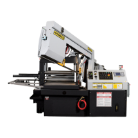
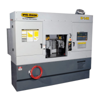
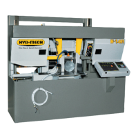
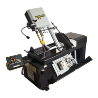
Images and descriptions of key electrical components like motors and pumps.

Limit Switches and Sensors

Description of limit switches and encoders.

Electrical Components, Continued

Shuttle and Proximity Sensors

Details on shuttle encoder and proximity sensor.

Optional Digital Angle Display

Description of the optional digital angle display encoder.

List of M16_M20 Electrical Components

List of M16_M20 Electrical Components

Options

List of optional electrical components.

M16 Power Components for Specific Voltages

M20 Power Components for Specific Voltages

Electrical Schematic

Electrical Wiring

Electrical Wiring

Section 5: Hydraulic System

M-16 Hydraulic Components List

M-20 Hydraulic Components List

Cylinder Piston Assembly

Cylinder Gland Assembly

Hydraulic Schematic M16/20

Hydraulic Piping Diagram

Section 6: Mechanical Assemblies

Blade Brush Assembly

Guide Arm & Carbide Guide Assemblies

Guide Arm & Carbide Guide Assemblies, Parts Lists

Blade Tension Assembly

Pivot Link Assembly

Hydraulic Tank Assembly

Hydraulic Pump Assembly

Front Vise & Conveyor Assembly

Front Vise & Conveyor, Parts List

Shuttle Vise Assembly

Shuttle Datum Jaw Assembly

Length Control Assembly

Chip Auger Assembly

Coolant Group

Doors and Covers

Drive Assembly, Parts Lists

M16 Drive Assembly, Parts Lists

M20 Drive Assembly, Parts Lists

Gear Box Assembly

Gear Box Assembly

Section 7: Optional Assemblies

Bundling Assembly

Bundling Assembly

Vertical Roller Assembly

M-16A Direct Drive Assembly

M-20A Direct Drive Assembly

Mitsubishi PLC 500 Controller

PLC 500 Operator Interface and Options

Overview of the PLC 500 interface and available options.

Section 8: Specifications

M-16 Specification List

M-16 Foundation Plan

Specification M-20

M-20 Foundation Plan

M-20 Foundation Plan

M-20 Foundation Plan

Section 9: Warranty

Related product manuals