COOLANT FLOW
A generous flow of coolant should be applied in order to increase production and blade life.
Machine is provided with two independently controlled coolant spouts.
- One from the adjustable guide arm nozzle. This one should always flood the blade with coolant. Slight
readjustment may be required when changing the blade speed. A properly adjusted flow of coolant should cover
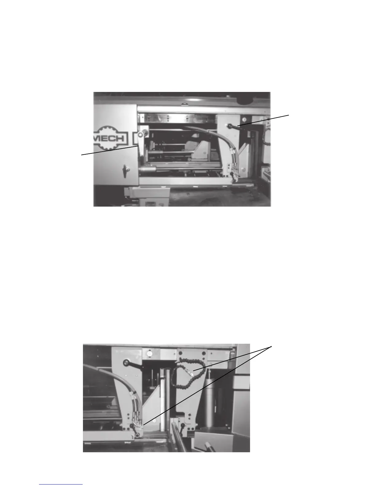
the blade which in turn will carry it into the cutting area. Flow adjusting tap is shown in Fig. 2C-4.
- The coolant hose on the fixed guide arm should be used in cases when cutting solid bars, bundles or wide
structurals. The flow of coolant should be directed into the opening created by the blade. Flow adjusting tap is
shown Fig. 2C-4.
NOTE: When cutting materials that do not need coolant (cast iron) some coolant flow is required to provide
blade lubrication to prevent blade scoring by carbides.
Fig. 2C-4
Coolant Flow
Adjusting Taps
GUIDE ARM POSITIONING
It is desirable, in order to maintain maximum beam strength in the blade, to keep the guides as close together
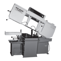
as possible. This span is obviously determined by stock size. As shown in Fig. 2C-3 ,in order to increase or
decrease the span between the guide arms, simply undo the guide arm lock handle A and move the guide arm
closer to or further away from the other guide via the rack-and-pinion crank B. We cannot overstress the
importance to performance of keeping blade span to a minimum.
Fig. 2C-3
B
A
2.23



 To Next Page