SECTION 5 - HYDRAULIC SYSTEM
The S-25A hydraulic system does not require any special work on a new machine before its start-up. The
hydraulic tank is filled with Valvoline 150-46 hydraulic oil and all machine functions have been tested at the
factory to ensure proper operation upon initial start-up.
PARTS LIST AND PHOTOS OF HYDRAULIC COMPONENTS
ITEM QTY DESCRIPTION OF PART PART NUMBER
1 1 Head Cylinder S25-C4-00
2 1 Shuttle Cylinder S25-C1-00
3 1 Blade Tension Cylinder S25-C5-00
4 3 Vice Cylinders S25-C3-00
5 1 Head Swing Cylinder S25-C9-00
6 3 Bundling Cylinder (Optional) S25-C23-00
7 1 Remote Blade Speed Cylinder (Optional) VSL-C9-00
8 1 Head Force Servo Valve T25-325-00
9 1 Positive Downfeed Valve DF2-0-00
10 1 Extension Block 2 position (Optional) EB-01
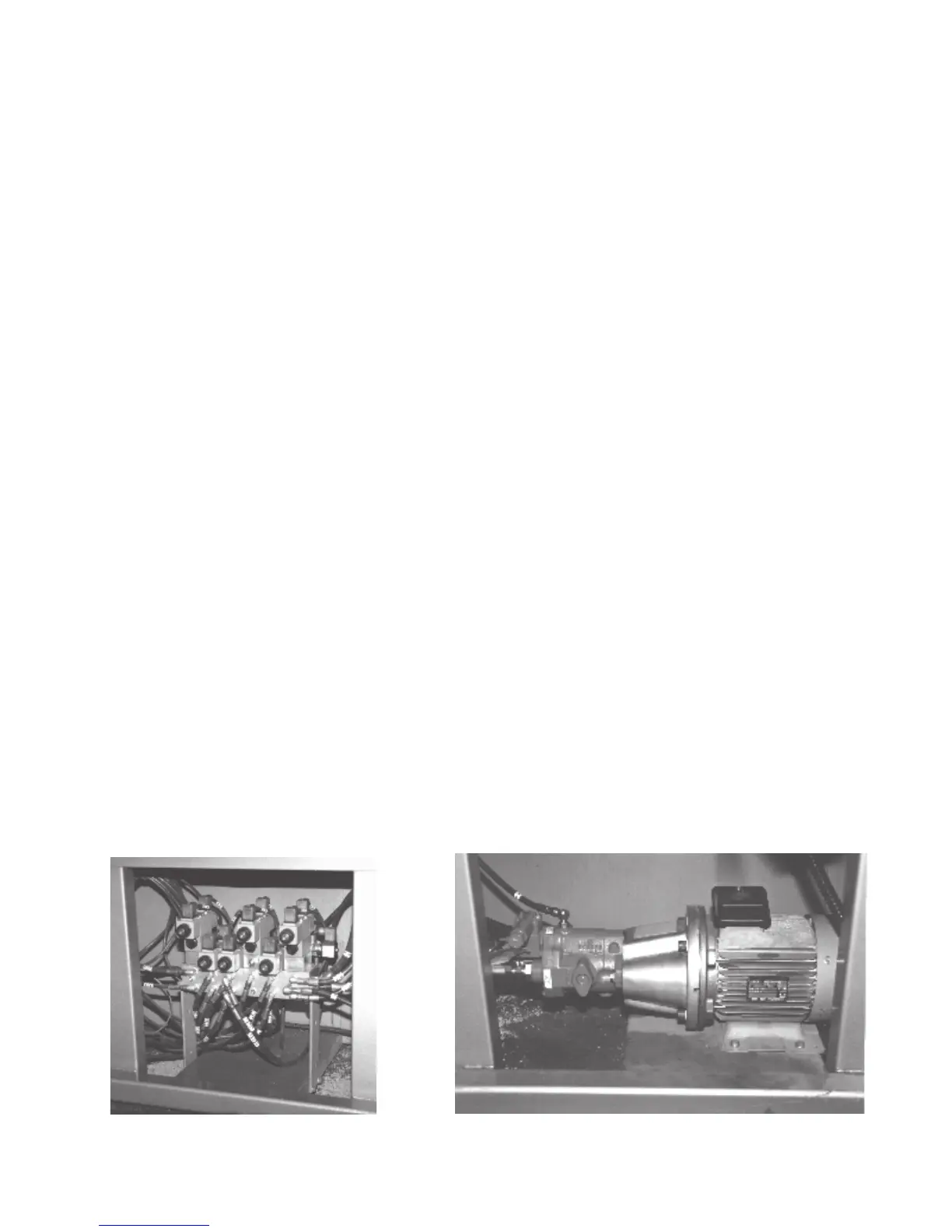
11 1 Manifold Block MB6P
12 3 Double Pilot Check DPCH-1
13 2 Pressure Gauge (1000 psi) PG-10
14 2 Pressure Gauge (500 psi) PG-5
15 2 Vice Valves DCV3P-AB-C
16 1 Remote Blade Speed Adjustment Valve (Optional) DCV3P-AB-T
17 1 Head Lift Valve DCV3P-AB-T
18 1 Head Swing Valve DCV3P-AB-T
19 1 Blade Tension Valve DCV3P-AB-C
20 1 Shuttle Valve DCV3P-AB-T
21 1 Relief Valve RV22-00
22 2 Poppet Valve PV2P-A-C
23 1 Swing Cushion Block CHB-15
24 1 Shuttle Cushion Block CHB-35
25 3 "o" Ring Plate MH-01
26 1 Pump HYP-1
27 1 Suction Strainer ZINGA SS-100-00
28 1 Return Filter ZINGA AE-10
Fig. 5-2 Pump Motor AssemblyFig. 5-1 Hydraulic Manifold
or GRESEN K-2201
5.1


 To Next Page