SECTION 4 - ELECTRICAL SYSTEM
GENERAL INFORMATION
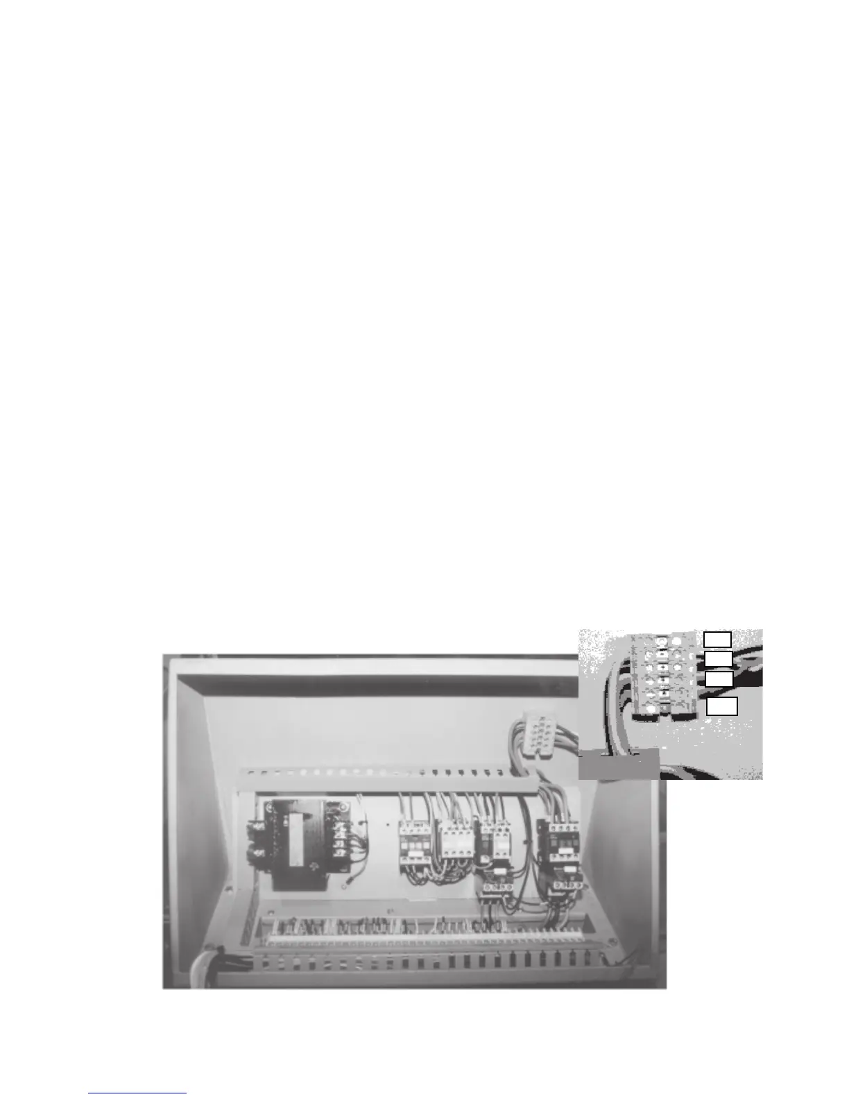
The power connection to the machine is made to the L1, L2 and L3 terminals of the contactor located in the
main control box. As supplied, the machine is set to run on three phase voltage as indicated on the serial plate
and the voltage label.
In order to use the machine on a different supply voltage the following changes must be made:
1. Change the blade motor (or if equipped with a dual voltage motor, rewire it)
2. Change the hydraulic pump motor (or if equipped with a dual voltage motor, rewire it)
3. Change the control transformer (or if equipped with a dual voltage unit, rewire it)
4. Change the blade and pump motor overloads, located adjacent to the contactor, to suit the full load
current of the new or rewired motor.
All other components are supplied from the control transformer and operate on 115V, single phase. They do not
need altering.
The machine is supplied for use on a 60HZ supply. For use on a 50HZ supply consult the factory.
WHEN CHANGING THE SUPPLY VOLTAGE, CAREFULLY OBSERVE THE ABOVE STEPS. THESE STEPS
ARE ESSENTIAL TO AVOID SEVERE DAMAGE TO THE MOTOR AND CONTROLS.
At initial hook-up it is important to check that the phase order is correct. This is indicated by the blade drive
wheel revolving in a counterclockwise direction and the hydraulic pressure gauge registering a pressure rise.On
the following pages are the electrical schematics and physical wiring diagrams along with a list of electrical
components.
4.1
PHOTOS OF STANDARD ELECTRICAL COMPONENTS
Fig. 4-1 Inside of the standard electrical control box.
2M
TR 1CR 2 CR 1 M
L 1
L 2
L 3
GND



 To Next Page