HOSE # HOSE TO CYLINDER CONNECTING HOSE
CONNECTION AT JUNCTION BLOCK
34 ROD END (FRONT VISE) 32
33 PISTON END 31
24 ROD END (SHUTTLE VISE) 22
23 PISTON END 21
34C ROD END (AUX. VISE) 32C
33C PISTON 31C
TABLE 1
1.2
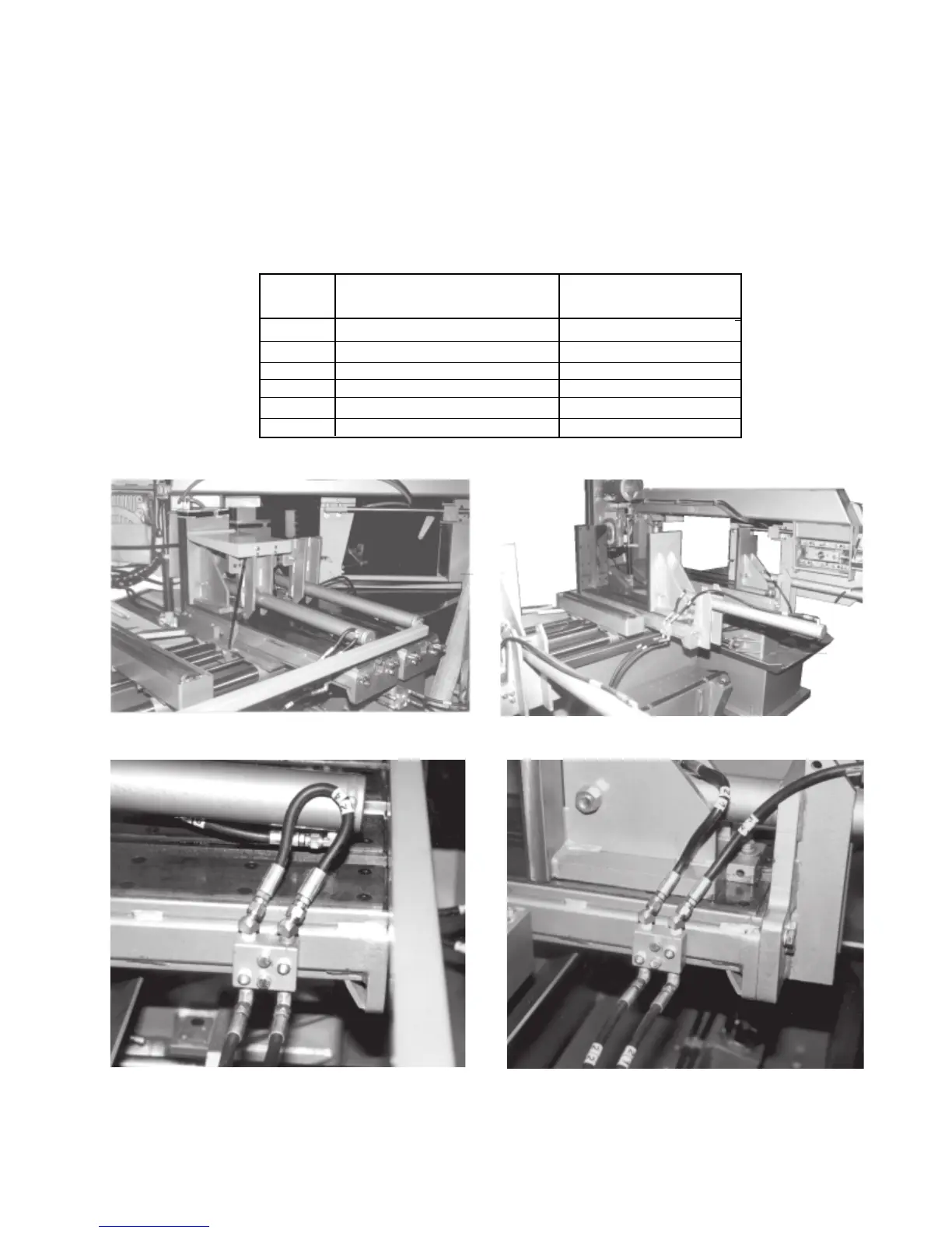
Fig. 1-4 Reassembled vises.
Fig. 1-3 Vises disassembled for shipping.
Fig. 1-5 Junction block plumed for shipping.
Fig. 1-6 Vise cylinder plumed to junction block.
VISE CYLINDERS
To permit the S-25A to be shipped in a standard trailer, the three vise cylinders must be fully retracted, the
hydraulic hoses disconnected, and the mounting brackets unbolted from the infeed table Fig. 1-3. The cylinder
tube is then rotated around the cylinder rod so that the mounting bracket and tube are upside-down. This jaw
is now pushed completely toward the fixed jaw letting the bracket rest on the infeed table. Before the initial
start-up, reinstall the vise bracket and reconnect the vise cylinder hoses Fig. 1-4. TABLE 1 lists the hose
reconnections, Fig 1-5 shows one of the junction blocks as it appears when machine is shipped. Fig. 1-6
shows a junction block after the vise cylinder hoses have been reconnected.



 To Next Page