Boxxer 421 Owner’s Manual
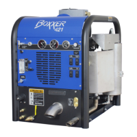
Boxxer 421
Machine Assemblies and Parts Lists ................................................. 11-1
Fig. 11-7 Frame Assembly - Front View ........................................... 11-2
Fig. 11-8 Frame Assembly - Rear View - Left Side ........................... 11-3
Fig. 11-9 Frame Assembly - Rear View - Right Side......................... 11-4
Fig. 11-10 70 Gallon Universal Recovery Tank Assembly .................... 11-7
Fig. 11-11 70 Gallon Universal Recovery Tank Cover Assembly .......... 11-10
Fig. 11-12 Dash Assembly ................................................................. 11-11
Fig. 11-13 Electrical Control Panel Assembly ..................................... 11-13
Fig. 11-14 Blower Heat Exchanger Assembly ..................................... 11-15
Fig. 11-15 Water Box Assembly ......................................................... 11-16
Fig. 11-16 Hydra Pump II Assembly .................................................... 11-18
Fig. 11-17 Chemical Pump Assembly ................................................. 11-20
Fig. 11-18 Fuel Pump Assembly ......................................................... 11-21
Fig. 11-19 Blower Assembly ............................................................... 11-22
Fig. 11-20 Vacuum Relief Valve (Collector Box) Assembly .................. 11-25
Fig. 11-21 Exhaust Assembly ............................................................. 11-26
Fig. 11-22 Diverter Valve Actuator Assembly ...................................... 11-28
Fig. 11-23 Hi PSI Manifold Assembly ................................................. 11-29
Fig. 11-24 Bypass Valve Assembly .................................................... 11-31
Fig. 11-25 Engine Assembly .............................................................. 11-33
Fig. 11-26 Briggs & Stratton Voltage Regulator Modification .............. 11-35
Fig. 11-27 Dura-Flow APO Pump Assembly ....................................... 11-36
Fig. 11-28 100 Gallon Universal Recovery Tank Assembly .................. 11-38
Fig. 11-29 100 Gallon Universal Recovery Tank Cover Assembly ........ 11-41