EasyManuals Logo

Hypertherm Powermax 30 User Manual

Hypertherm Powermax 30
88 pages
To Next Page IconTo Next Page
To Previous Page IconTo Previous Page
Page #64 background imageLoading...
Page #64 background image
MAINTENANCE
powermax30 Service Manual 3-25
4. Carefully tilt the front endcap away from the power supply. The orange, blue, and purple wires from the torch
lead are connected to the power board with a 3-pin connector at J12. Remove the connector by pulling it toward
the front of the power supply.
J12
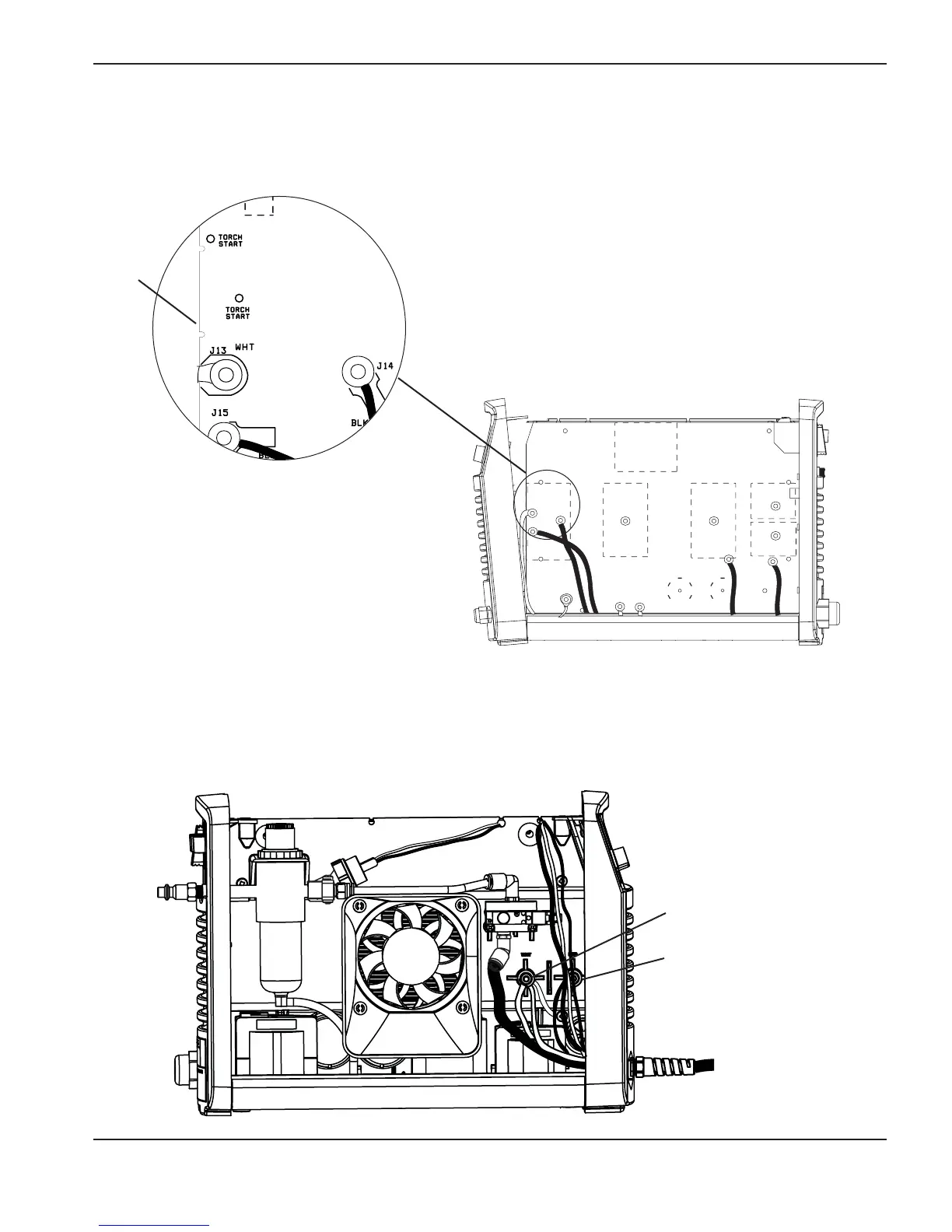
5. The white wire group and the red wire from the torch lead are secured to studs in the power supply’s center
panel on the fan side of the power supply. Use a 5/16-inch (8 mm) nut driver to remove the nuts from the studs
and slide the ring terminals off the studs.
White wire group
Red wire

Table of Contents

Questions and Answers:

Question and Answer IconNeed help?

Do you have a question about the Hypertherm Powermax 30 and is the answer not in the manual?

Hypertherm Powermax 30 Specifications

General IconGeneral
Gas Pressure5.2 bar (75 psi)
TorchHand Torch
Input Voltage120-240 V
Input Phase1
Current Output20-30 A
Cutting Thickness10 mm (3/8 inch)
Max Severance Thickness16 mm (5/8")
Max Clean Cut Thickness10 mm (3/8 inch)
Weight9.5 kg (21 lbs)
Gas TypeAir
Dimensions356 mm D x 168 mm W x 305 mm H (14" D x 6.6" W x 12" H)

Related product manuals