MAINTENANCE
1
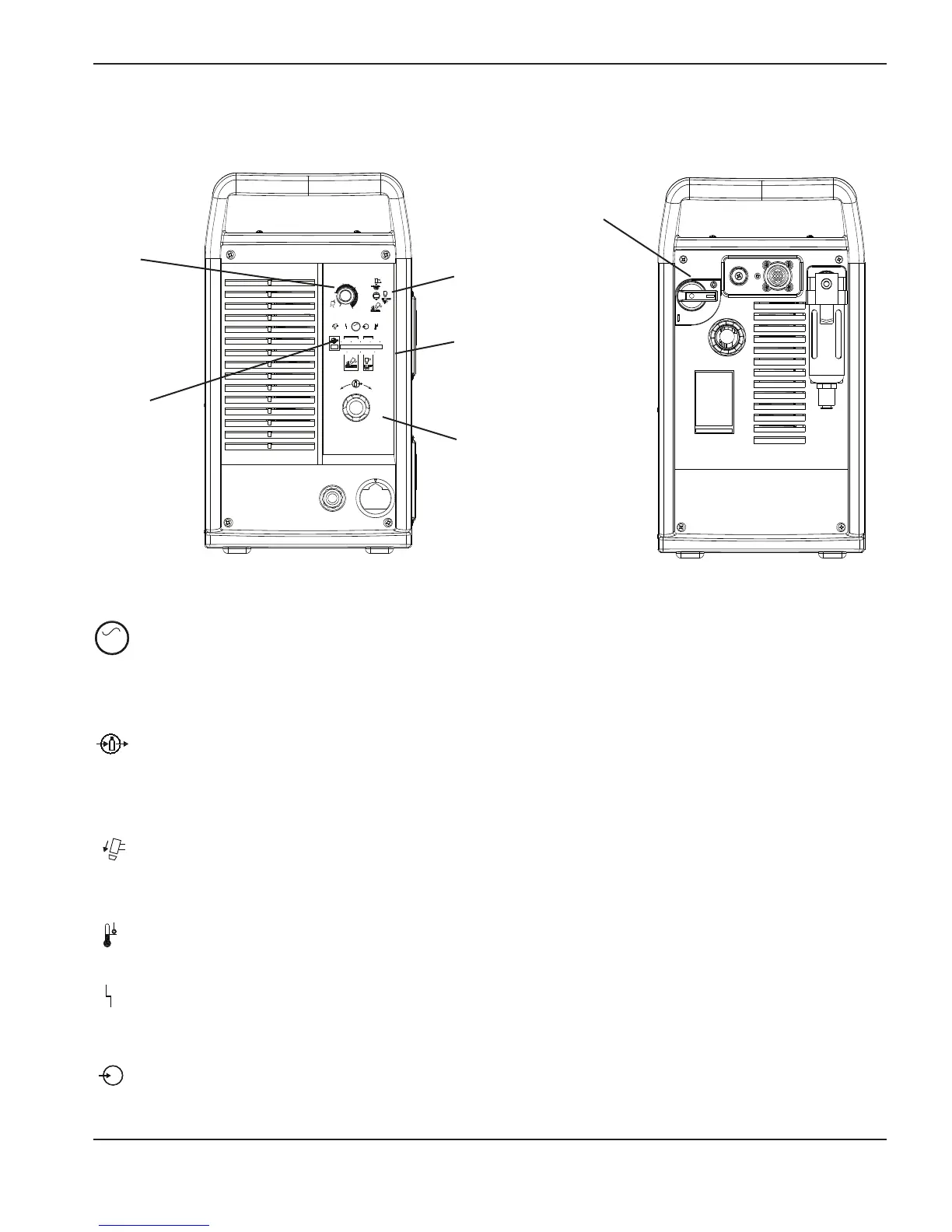
Controls and indicators
6.0
B
AR
5.04.0
PSI
80705060
6
0
40
AMPS
80
25
V
AC
+
_
Current
(amps)
adjustment
knob
Mode switch
I
ndicator
L
EDs
Pressure
gauge
Pressure
regulator
ON (I) / OFF (O)
switch (S1)
Green power ON LED
When illuminated, indicates that power is applied to the system and the power switch is ON (I).
Note: The LED should illuminate when the power is ON (|).
Gas pressure LED
Yellow: When flashing, indicates that the gas pressure is below 60 psig (4.1 bar) for cutting, or 40 psig
(2.8 bar) for gouging.
Green: When illuminated, indicates acceptable gas pressure for torch operation.
Note: The LED should illuminate when the power is ON (|).
Y
ellow torch cap LED
When illuminated, indicates that the retaining cap is loose or not installed.
Note: Turn the power OFF, correct this fault condition, then turn ON the power to extinguish the LED.
Yellow temp LED
When illuminated, indicates that the power supply’s temperature is too hot.
Red fault LED
When illuminated, indicates that a fault condition exists, which prevents system operation.
Yellow low line voltage LED
When illuminated, indicates that line voltage is below 170 VAC or above 680 VAC. On CE units, it can
also indicate a missing phase.
Indicator LEDs
powermax1000 Service Manual 3-3