MAINTENANCE
3-20 powermax1000 Service Manual
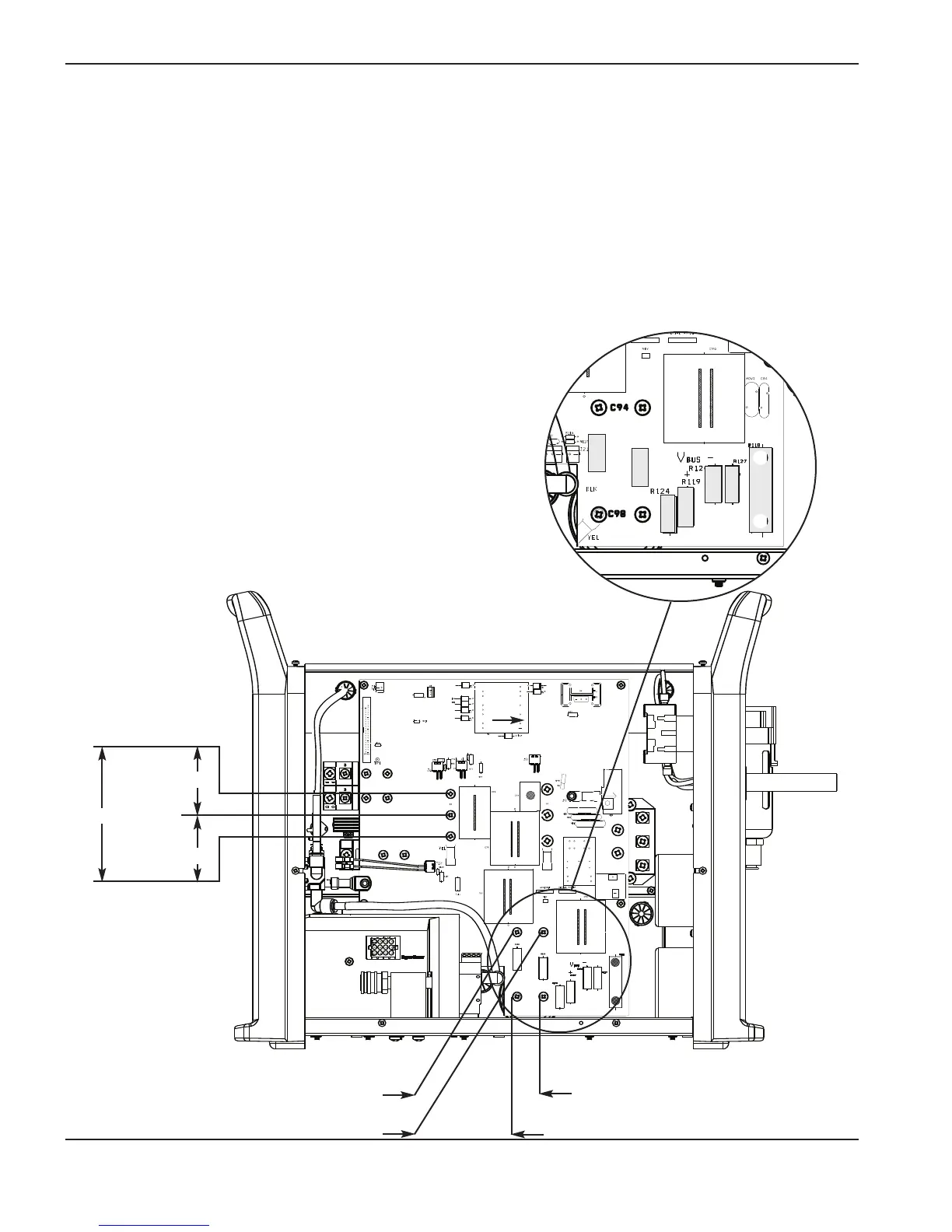
1
Test 2 – voltage balance
Test to check the balance of the bus voltage, the power-factor circuit, and the soft-start circuit.
•
Verify the system’s serial number. Serial numbers lower than 1000-016236 have a different power board
from systems with serial numbers higher than 1000-016236.
• Remove screws from capacitors C94 and C98 before measuring the resistors listed below.
• Check the voltage across the inverter IGBT (Q6).
• Check the voltage across the capacitors (C94, C98) before and during torch operation.
• Voltage across both capacitors should be 375 VDC.
On systems with serial numbers below 1000-016236, if the capacitors are not balanced at 375 VDC, install the
RCD resistor kit (PN 128963). For systems with higher serial numbers, replace the power board.
Note: All values can be ±15%.
750 VDC
375 VDC
375 VDC
C94
375 VDC
C98
375 VDC
Bus-bleed and soft-start
resistors for serial numbers
above 1000-016236.
R124 = 75kΩ
R125 = 75kΩ
R126 = 75kΩ
R127 = 75kΩ
Bus-bleed and soft-start
resistors for serial numbers
below 1000-016236.
R118 = 3Ω
R119 = 25kΩ
R120 = 25kΩ
Note: Bulk capacitors must be
out of circuit.
R126 = 20.8k R120 = 21.2k
R125 = 21.0k R127 = 21.2k
R124 = 24.1k
R119 = 24.1k
Inverter IGBT (Q6)