MAINTENANCE
3-10 powermax1000 Service Manual
1
C
aution: Failure to isolate the IGBT may result in false readings and/or damage
to the IGBT tester.
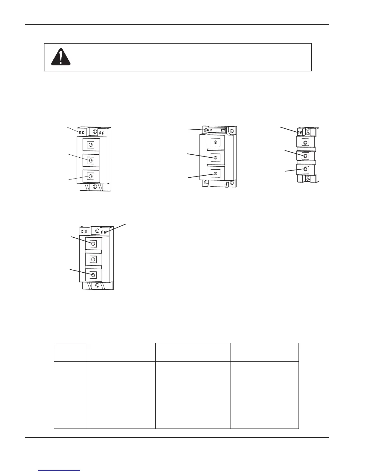
The illustrations below depict three common IGBT configurations. Each connection on the IGBT is labeled with an
a
bbreviation. They may be labeled as C, E, G or 1, 2, 3 with a schematic that shows numbers and pin functions.
Yellow lead
Gate 1 (G1)
Black lead
Emitter 1 (E1)
Red lead
Collector 1, (C1)
IGBT, Inverter,
Test 2
Yellow lead
Gate (G)
Black lead
Emitter (E)
Red lead
Collector (C)
IGBT, PFC
Yellow lead
Gate (G)
Red lead
Collector (C)
Black lead
Emitter (E)
IGBT, Pilot arc
IGBT device test using the Hypertherm tester
Using the Hypertherm IGBT tester, press and hold the switch in the desired position to perform the tests described
in the following table.
Switch
LED
position Fail Pass Battery This may mean Corrective action
Left X – – IGBT is shorted Replace IGBT
Left – X – IGBT passed short test None
Left – – X Battery below 8V Replace battery
Left – – – Dead battery Replace battery
Right X – – IGBT is open Replace IGBT
Right – X – IGBT passed open test None
Right
– – X Battery below 8V Replace battery
Right – – – Dead battery Replace battery
IGBT, Inverter,
Test 1
Yellow lead
Gate 2 (G2)
Black lead
Emitter 2 (E2)
Red lead
Collector 2 (C2)