EasyManuals Logo

Hypertherm powermax1250 Service Manual

Hypertherm powermax1250
98 pages
To Next Page IconTo Next Page
To Previous Page IconTo Previous Page
Page #60 background imageLoading...
Page #60 background image
MAINTENANCE
powermax1250 Service Manual 3-27
4
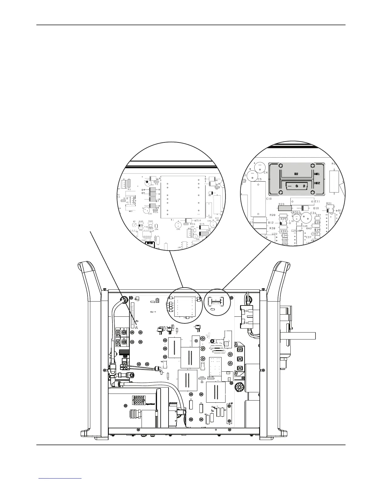
Test 6 – flyback circuit
DC power supply circuit test (+5 VDC, +10 VDC, +18 VDC, and +24 VDC).
Verify that the diodes listed below are not short-circuited by checking their resistance (approximately 2k).
Note: Check the voltage to TP1.
Inspect the circuit for damage.
D4 = 24 VDC R1 = 24 VDC
D5 = 24 VDC R2 = 18 VDC
D7 = 10 VDC R9 = -6 VDC
D9 = 18 VDC R18 = 5 VDC
D17 = 5 VDC R20 = 0.75
R26 = 18 VDC
R55 = 18 VDC
80
80
TP1

Table of Contents

Other manuals for Hypertherm powermax1250

Questions and Answers:

Question and Answer IconNeed help?

Do you have a question about the Hypertherm powermax1250 and is the answer not in the manual?

Hypertherm powermax1250 Specifications

General IconGeneral
BrandHypertherm
Modelpowermax1250
CategoryWelding System
LanguageEnglish

Related product manuals