MAINTENANCE
3-30 powermax1250 Service Manual
4
Test 10 – gas solenoid
• If the gas flows continuously, disconnect the gas solenoid connector (J20) from the power board (PCB2). If
the gas does not shut off, replace the valve.
• If the gas stops, disconnect the ribbon cable (J4) from the power board (PCB2) and reconnect J20. If the
gas remains off, replace the control board (PCB3). If the gas flow returns, replace the power board (PCB2).
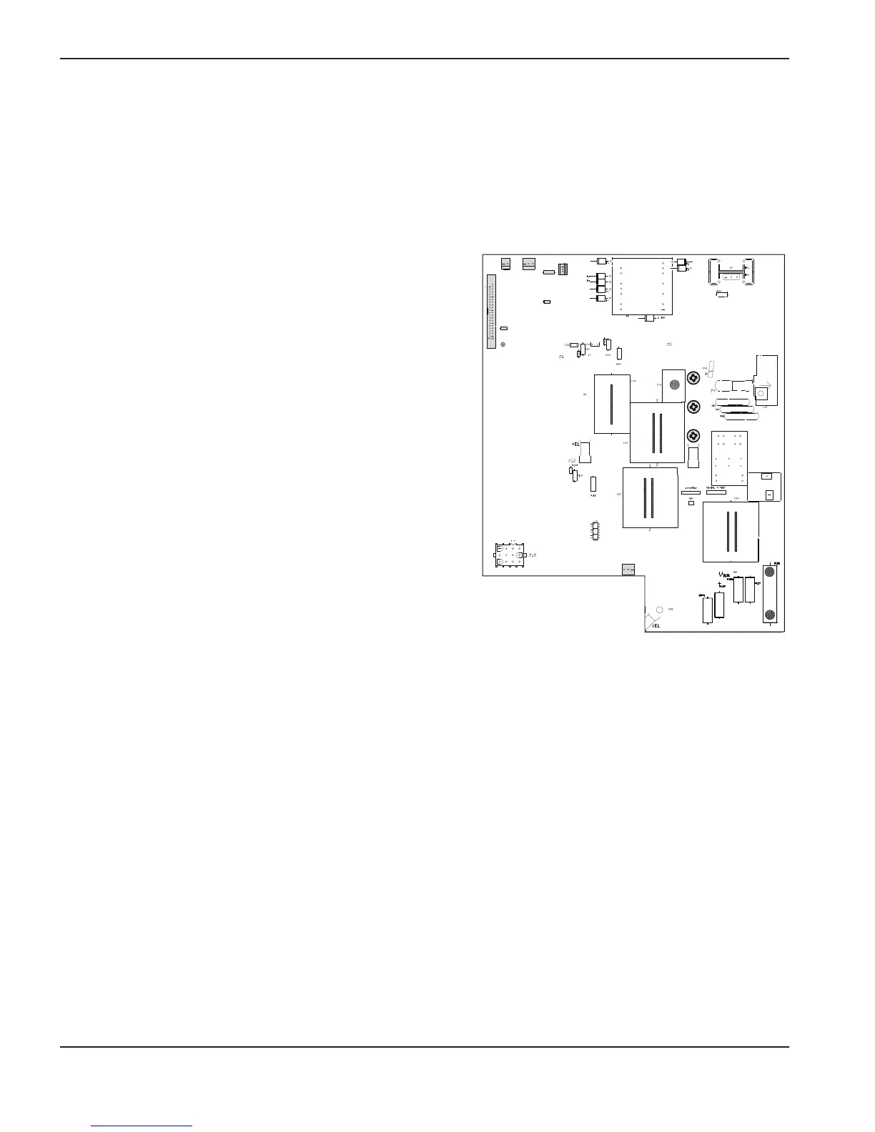
Test 11 – incoming line voltage (VACR)
• Verify that the voltage on output of the input diode,
equals 1.414 multiplied by the input voltage.
• If the value is low, check the input voltage or replace
the diode.
• If the value is correct, verify that the voltage between
the left side of R25 and ground (TP1) is 4.969 mV/V.
• If the value is correct, replace the control board
(PCB3). If not, replace the power board (PCB2) and
the PFC IGBT (Q7).
Test 12 – pressure switch
• Verify that the voltage from the right side of R50 to
ground (TP1) reads approximately 0.0463 VDC
multiplied by psi. For example, when the air regulator is
set to 80 psi, the voltage should be approximately
3.7 VDC.
• If the value is correct, replace the control board
(PCB3). If not, replace the pressure switch.
Test 13 – fan
• Force the fan into an over-temperature condition (place a jumper wire from J2 pin 1 to pin 2 to short it).
• Verify that the voltage across the fan on power board (PCB2) J1 pins 1 and 2 equals 24 VDC.
– If it does not, remove the fan connector (J1) and check the voltage on the power board (PCB2) J1 pins 1
and 2 again.
–
If it equals 24 VDC now, continue to the next step. If not, perform T
est 6 – flyback circuit.
•
Place a jumper wire between the fan transistor (Q1) case to ground (TP1). If the fan turns on, continue to
the next step. If not, replace the fan.
• Check the voltage between the left side of R7 and ground (TP1). If the VDC is zero (0), replace the control
board (PCB3). If the value is 5 VDC, replace the power board (PCB2).

 Loading...


