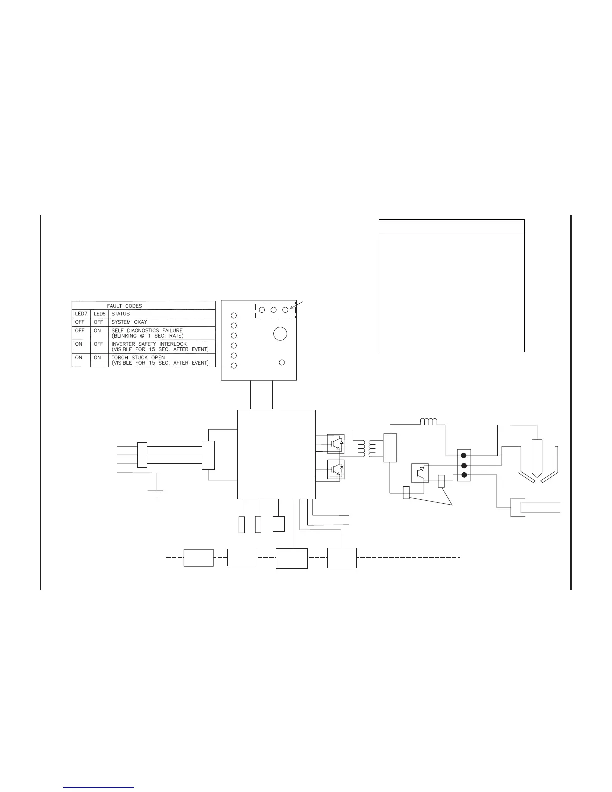
Designator Component
D18 .................. Input diode bridge
D2 .................... Output diode
L2 ..................... Output choke inductor
M1 .................... Fan
PCB2 ................ Power board
PCB3 ................ Control board
PS1 .................. Pressure switch
Q2 .................... IGBT module
Q3 .................... Pilot arc IGBT
S1 ..................... Breaker
TB1 .................. Terminal block
TS1 .................. Heatsink temperature sensor
TS2 .................. Transformer temperature sensor
T2 ..................... Power transformer
V1 ..................... Solenoid valve
Figure 3-2.2 Powermax600 208-240/480 Volt Block Diagram
10-99

 Loading...


