2-6
SPECIFICATIONS
Service Manual
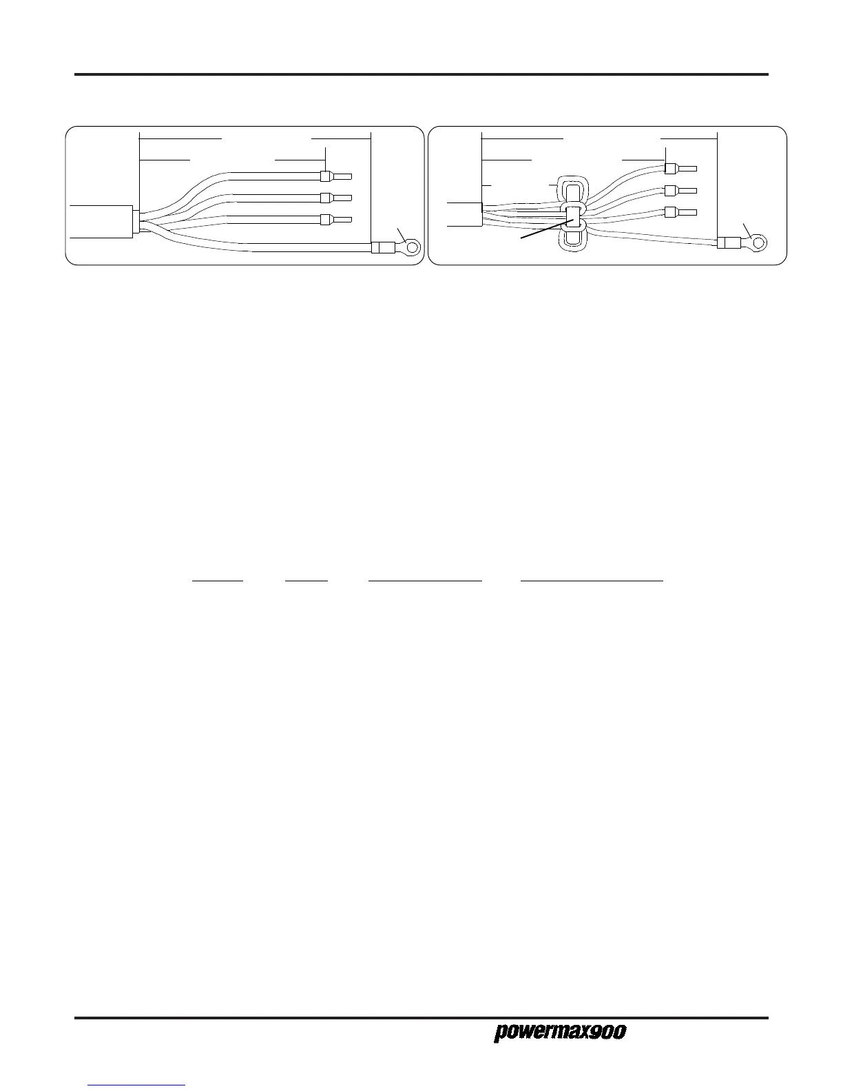
4.5" (114 mm)
3.5" (89 mm)
Figure 2-5 Power Cord Preparation - Non-CE
L1
L2
L3
Ground
#10
Figure 2-6 Power Cord Preparation - CE
4.75" (120 mm)
3.75" (95 mm)
L1
L3
#10
L2
0.5" (13 mm)
Ground
All wires 1 turn
through 109068 toroid.
Power Requirements
Line Voltage Disconnect Box
Use a line disconnect box for each power supply. This disconnect box allows the operator to turn the
power supply off quickly in an emergency situation. The switch should be located on a wall near the
power supply, and should be easily accessible to the operator. The interrupt level of the switch must be
equal to or exceed the continuous rating of the fuses. Use slow-blow fuses according to the power
requirements listed below.
Input Input Current Recommended
Voltage Phase @ 6.6 kw Output Slow-Blow Fuse Size
200 VAC 1 57 amps 70 amp
208 VAC 1 55 amps 70 amp
230 VAC 1 50 amps 70 amp
240 VAC 1 47 amps 60 amp
400 VAC 1 33 amps 40 amp
480 VAC 1 28 amps 35 amp
200 VAC 3 33 amps 40 amp
208 VAC 3 32 amps 40 amp
230 VAC 3 29 amps 35 amp
230 VAC (CE) 3 31 amps 40 amp
240 VAC 3 28 amps 35 amp
400 VAC 3 18 amps 25 amp
400 VAC (CE) 3 18 amps 25 amp
480 VAC 3 15 amps 20 amp
600 VAC 3 12 amps 20 amp