3-19
MAINTENANCE
Service Manual
Voltage Check #2 - Figure 3-12
• Voltage at Output of Input Diode Bridge
This DC voltage will approximately equal the line voltage X 1.414 - See table below.
Line Voltage Output at Bridge
200VAC ≈ 280VDC
208VAC ≈ 290VDC
230VAC ≈ 320VDC
240VAC ≈ 340VDC
400VAC ≈ 560VDC
480VAC ≈ 680VDC
≈ Line Voltage
X 1.414
See Table
14
13
Figure 3-12 Voltage Check #2 - Output of Input Diode Bridge
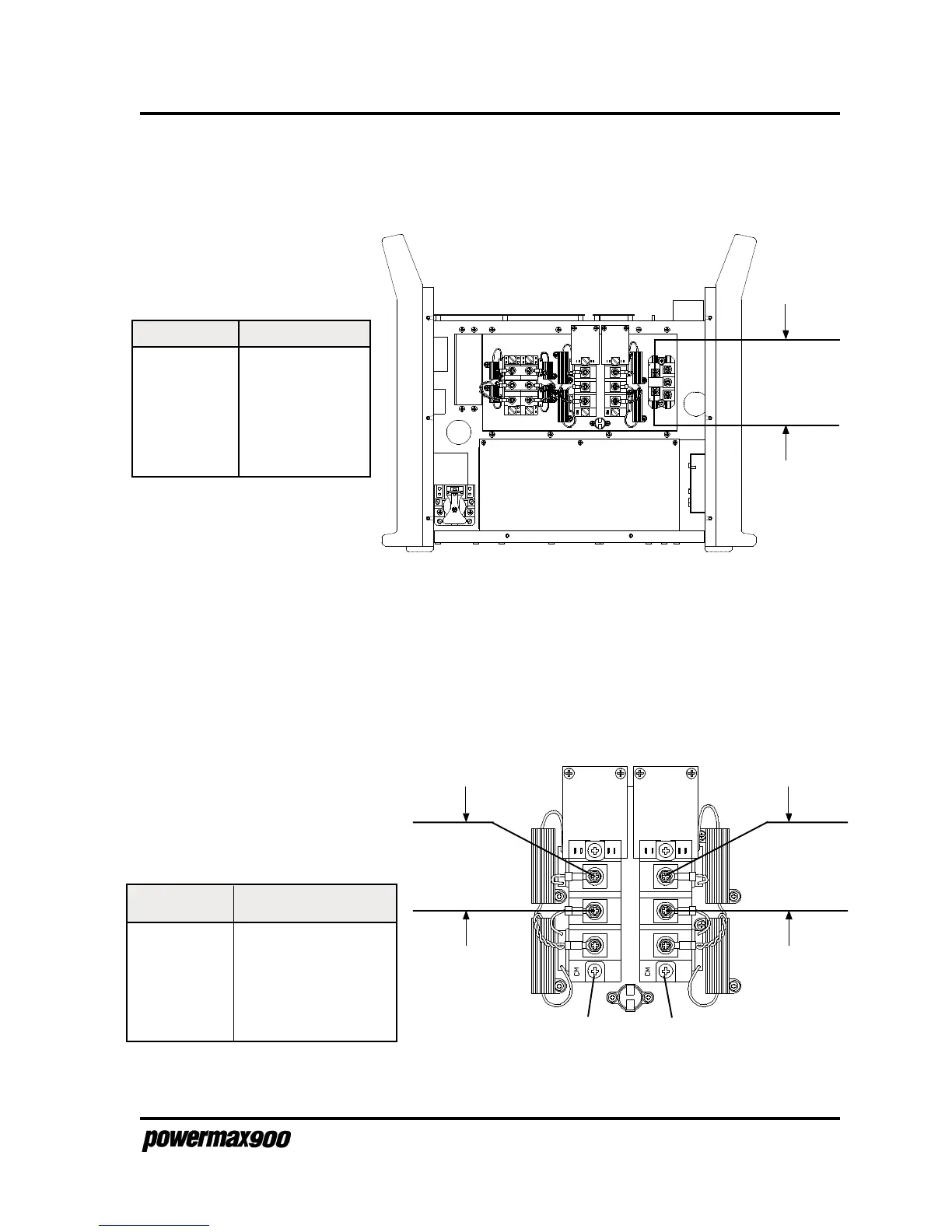
Voltage Check #3 - Figure 3-13
• Voltage Across Power Board Capacitors (taken at Q1 and Q2)
See the table in Figure 3-13 to find the correct voltage readings across the power board
capacitors.
Figure 3-13 Voltage Check #3 - Across Power Board Capacitors
Line Voltage Voltage across Wires
21&22 and 15&16
200VAC ≈ 280VDC
208VAC ≈ 290VDC
230VAC ≈ 320VDC
240VAC ≈ 340VDC
400VAC ≈ 280VDC
480VAC ≈ 340VDC
Q1
21
22
See Table
Q2
15
16
See Table