www.hysecurity.com © 2019 Photo Eye Installation MX3630-01 Rev. J 95
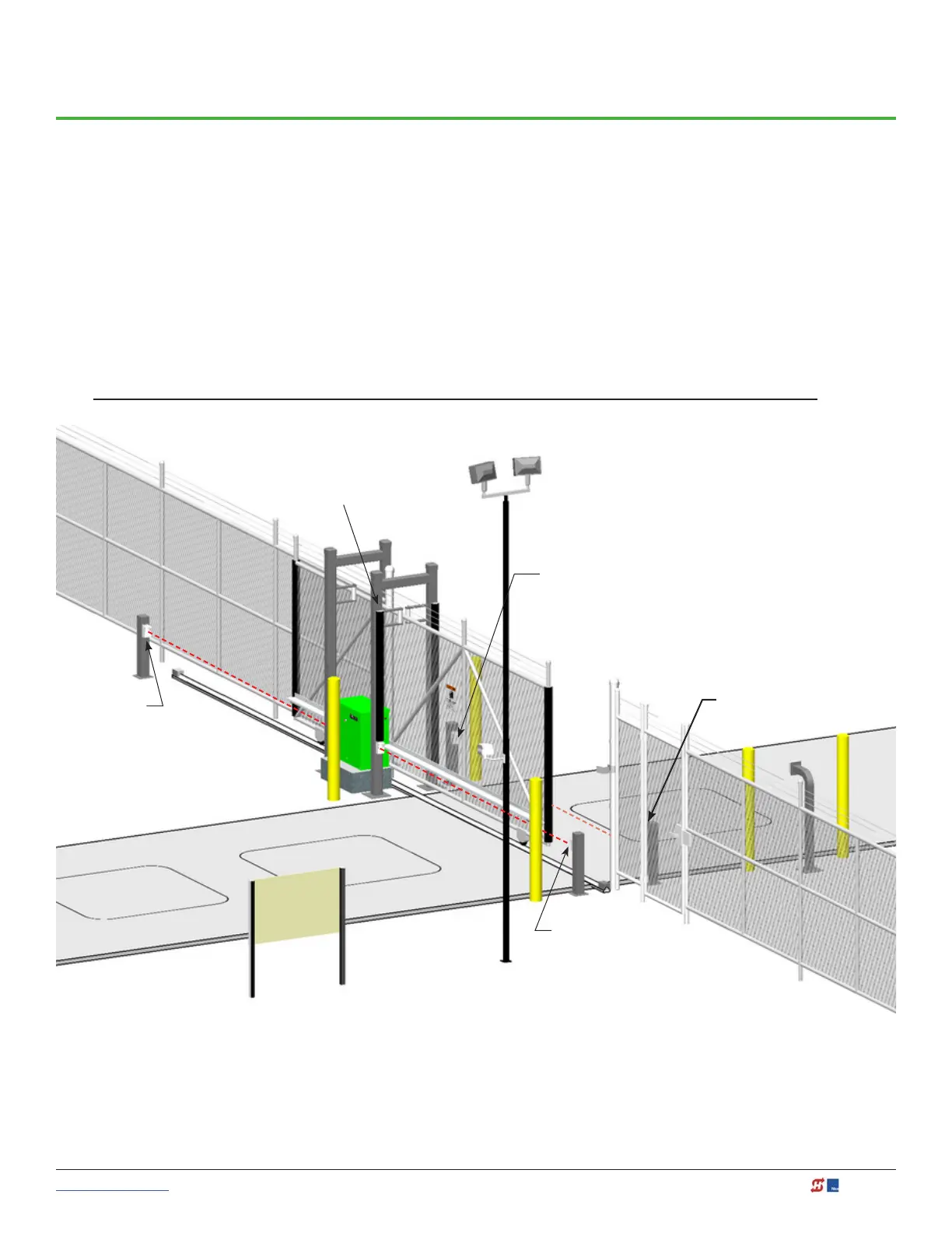
Photo Eye Installation
A monitored connection tests for the presence and correct operation of the photo eyes (and other monitored
sensors) prior to each gate activation. The monitored connection prevents gate operation if an entrapment
protection sensor is missing or any fault is present.
Sensors, such as gate edges and photoelectric beams, must be installed to protect against entrapment. These
external entrapment protection sensors are required for the gate installation to be in compliance with the
2018, UL 325 Standard of Safety (7th Edition).
NOTICE: UL 325 Standard of Safety provides the MINIMUM safety standards. Site, gate hardware usage,
and other conditions may dictate the use of additional safety designs/components. It is up to the gate system
designer and installer to assess appropriate safety design and components above and beyond minimum UL 325
and ASTM F2200 Standard of Safety. Always check your local area codes and comply with all regulations.
PUBLIC
SECURE
Photo Eye Close direction of travel
(public side)
Photo Eyes
(CLOSE direction of travel)
Photo Eyes
(OPEN direction of travel)
Photo Eye Close direction of
travel (public side)
NOTE: To enable fully automatic operation, this gate operator requires a MINIMUM of one external entrapment protection sensor
to monitor potential entrapment zones in either the open or close direction of travel. Visit www.hysecurity.com/gatesafety for more
information on UL 325 standards and gate safety.
To learn more about external entrapment protection devices or to learn how to temporarily supply power to
the sensors that are wired to the gate operator, review External Entrapment Protection Sensors: What the
Installer Needs to Do on page 40 and Supply Power to the Sensors on page 43.
Fixed Edge on Draw-in Post

 Loading...


