36 MX3630-01 Rev. J SlideDriver/SlideDriver 50VF Series © 2019 www.hysecurity.com
Entrapment Protection
As of January 2016, UL325 standard requires gate operators to monitor the presence of all external entrapment
sensors, including non-contact (Photo Eyes) and contact (Edge) sensors. For operators built between January
1st, 2016 and July 31st, 2018 only one external entrapment sensor is needed to allow automatic operation, but
all potential entrapment zones must be protected or eliminated. After July 31st, 2018, all Slide gate operators
will need a minimum of 2 external entrapment sensors (1 open direction and 1 close direction) installed before
automatic operation is allowed, but all potential entrapment zones must be protected or eliminated.
HySecurity monitors all external entrapment sensors connections by looking for NC contacts connected to
input terminals. Smart touch software cycles power to device and looks for a time delay from when device
powers on to when the contact closes (sensor input pulled low, meaning the sensor is not blocked/tripped).
Three programmable sensor inputs are available for use and must be programmed to a non-zero number
when initial conguration is performed. The three inputs are labeled Sensor 1, Sensor 2, and Sensor 3 and are
congurable in the installer menu (S1, S2, or S3) for the following options:
• 1 − Not Used
• 2 − Eye Close
• 3 − Edge Close
• 4 − Eye Open
• 5 − Edge Open
• 6 − Edge Both (Swing Only)
• 7 − Eye Both (Solo Slide Only)
It is the installers responsibility to determine the number of potential entrapment zones that exist and program
the Sensor inputs according to which type of external entrapment sensor will be used to protect each zone.
If more than three potential entrapment zones exist, then site design may be adjusted to eliminate risks or a
Miller Edge MIM- 62 may be used to connect additional sensors.
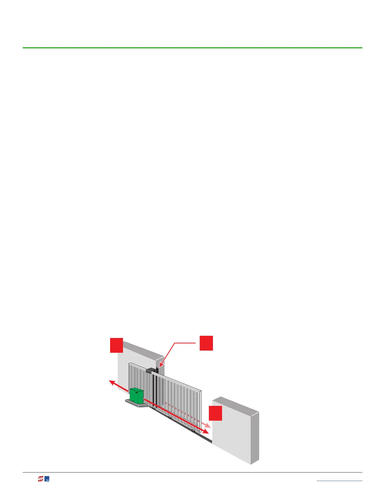
Potential entrapment zones on a hydraswing gate are shown below. Included in the drawing are examples of
potential external entrapment sensor mounting/installation locations.
Trailing End
3
Draw-in Zones
Wired edge sensors can
protect areas of entrapment
along posts or walls.
Public Side
1
Slide Gates:
Potential Zones for
Entrapment Protection
1. Draw-in zones
2. Leading end
3. Trailing end
Leading End
2
Secure Side

 Loading...


