2200 SRM 514 Curtis 1215 Display Panel Replacement
to the connector. After removing screws that fas-
ten front cover, carefully disconnect connector. It
can be necessary to disconnect key switch wires
(Step 4) and two-wire connector for enough clear-
ance to disconnect 18-pin connector. Remove two
screws that fasten LED assembly to housing. In-
stall replacement LED assembly. Carefully con-
nect all connectors and wires. Install front steer-
ing column cover with display panel assembly at-
tached. Install LED gasket over LED indicators.
8. If necessary, install new O-ring gasket. Care-
fully install O-ring gasket in groove of top cover.
Carefully install top cover assembly over LED in-
dicators and assembly housing without damag-
ing either LED gasket or O-ring gasket. Make
sure O-ring gasket is still correctly aligned with
cover and housing before installing screws. In-
stall eight screws that fasten top cover to panel
housing and tighten them in a cross pattern.
ENHANCED DISPLAY PANEL PARTS,
REPLACE
The only replaceable parts of the enhanced display
panel are the O-ring seal, key switch, wires to the
key switch, and the housing that fastens to the steer-
ing column. All other parts of the panel must be re-
placed as a single unit. See Display Panel Assembly,
Replace and Figure 3.
Curtis 1215 Display Panel Replacement
REMOVE
The Curtis 1215 Display Panel is located in the front
cover over the battery compartment. The display
panel cannot be repaired and must be replaced if it
is faulty.
1. Move lift truck to a safe, level area. Turn key
switch to OFF and remove key. Put a DO NOT
OPERATE tag on the multifunction control han-
dle. Put blocks under drive wheels to keep lift
truck from moving. Refer to How to Put Lift
Truck on Blocks in the section Periodic Main-
tenance.
WARNING
Discon
nect battery and separate connector be-
fore op
ening compartment cover or inspecting
or repa
iring electrical system. If a tool causes
ashort
circuit, the high-current flow from the
batter
y can cause an injury or parts damage.
2. Discon
nect and separate battery connector.
3. Remove
hydraulic tank dipstick.
4. Remove
socket head capscrews retaining battery
compa
rtment cover. Remove battery compart-
ment c
over.
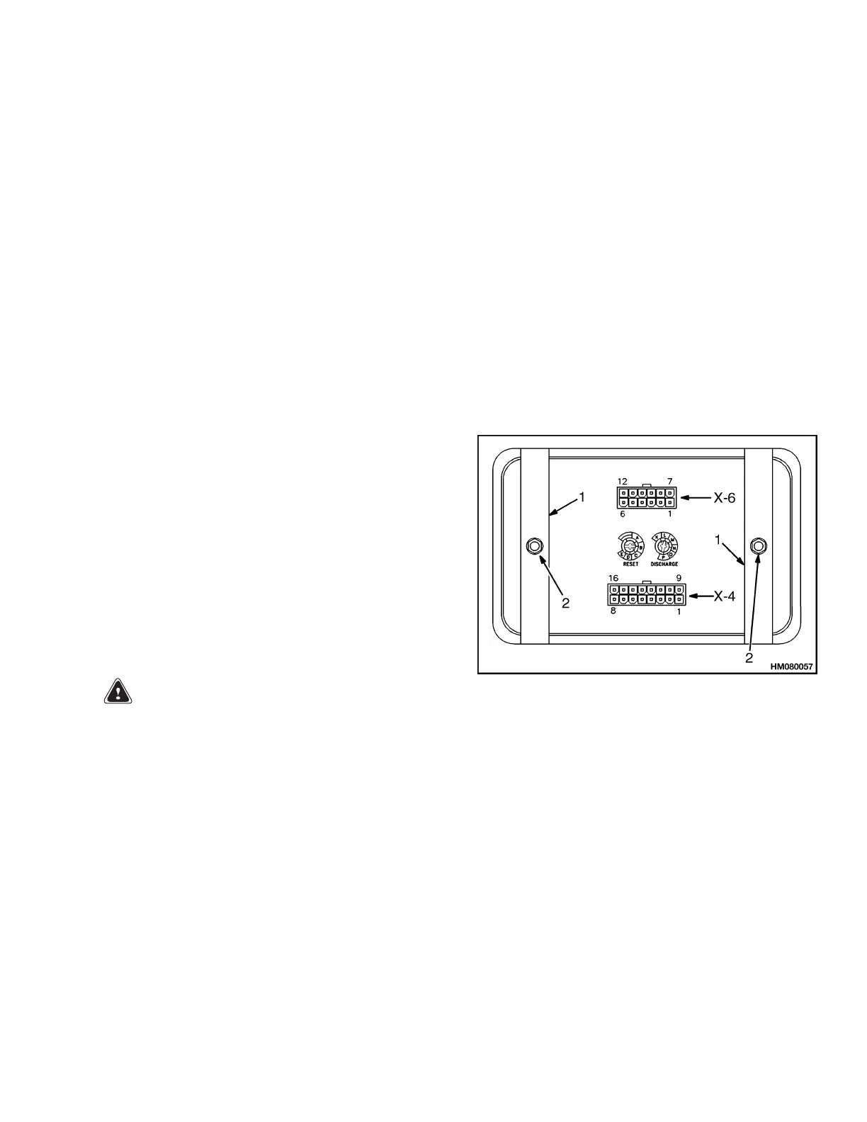
5. Disco
nnect two plugs X-4 and X-6 from rear of
displ
ay assembly.
6. Remov
e two nuts and brackets that fasten
displ
ay assembly to instrument panel. See Fig-
ure 10
. Remove display assembly.
1. MOUNT BRACKET 2. MOUNT NUT
Figure 10. Curtis 1215 Mount
INSTALL
1. Adjust pots on rear of dash display assembly.
2. Connect two plugs X-4 and X-6 to rear of dash
display.
3. Position display assembly in instrument panel.
Install nuts and brackets to rear of display to
fasten display assembly to instrument panel.
4. Install battery cover.
5. Reinstall hydraulic tank dipstick.
6. Remove blocks from under drive wheels. Remove
DO NOT OPERATE tag. Connect battery and
install key.
19
 Loading...