Cluster-Type Display Panel (Internal Combustion) Replacement 2200 SRM 514
indicators and corresponding drive modes to in-
creasefromTurtletoMidtoRabbit.Thefollow-
ing describes these modes as programmed from
the factory:
• Turtle mode provides slower acceleration, re-
duced top speed, and maximized energy effi-
ciency. It is also a valuable setting when train-
ing new operators.
• Mid mode reduces acceleration with full travel
speed.
• Rabbit mode provides maximum acceleration
and travel speed. When the key switch is
turned to OFF, the selected drive mode is
retained. When the battery is disconnected,
the drive mode returns to the Rabbit mode.
The rates of acceleration and travel speeds are
programmable and can be adjusted by a qualified
service technician. See the section Traction Mo-
torControllerandHandset2200 SRM 608 for
additional information. Refer to Programming
Traction Motor Controller.
5. The LED function selection lights display the se-
lected hydraulic function. Status messages will
be displayed for lift, tilt, reach, and sideshift.
The function selection lights will display the
current hydraulic function, independent of the
present LCD display.
The instrument display is powered when the key
switch is ON. The instrument panel contains
an internal backup battery that is capable of
memory retention of the battery indicator and
hourmeter readings when the battery is discon-
nected.
Cluster-Type Display Panel (Internal Combustion) Replacement
REMOVE AND DISASSEMBLE
CAUTION
To prevent damage to electrical components,
disconnect negative battery cable before re-
moving covers.
1. Remove steering control unit as described in the
following sections:
• Steering Housing and Control Unit 1600
SRM 512 for S/H2.00-3.20XM (S/H40-65XM)
• Steering Housing and Control Unit 1600
SRM 720 for S/H1.25-1.75XM, S/H2.00XMS
(S/H25-35XM, S/H40XMS)
NOTE: Newer instrument cluster panels have turn
signals that are red. The turn signals on older model
cluster panels are green.
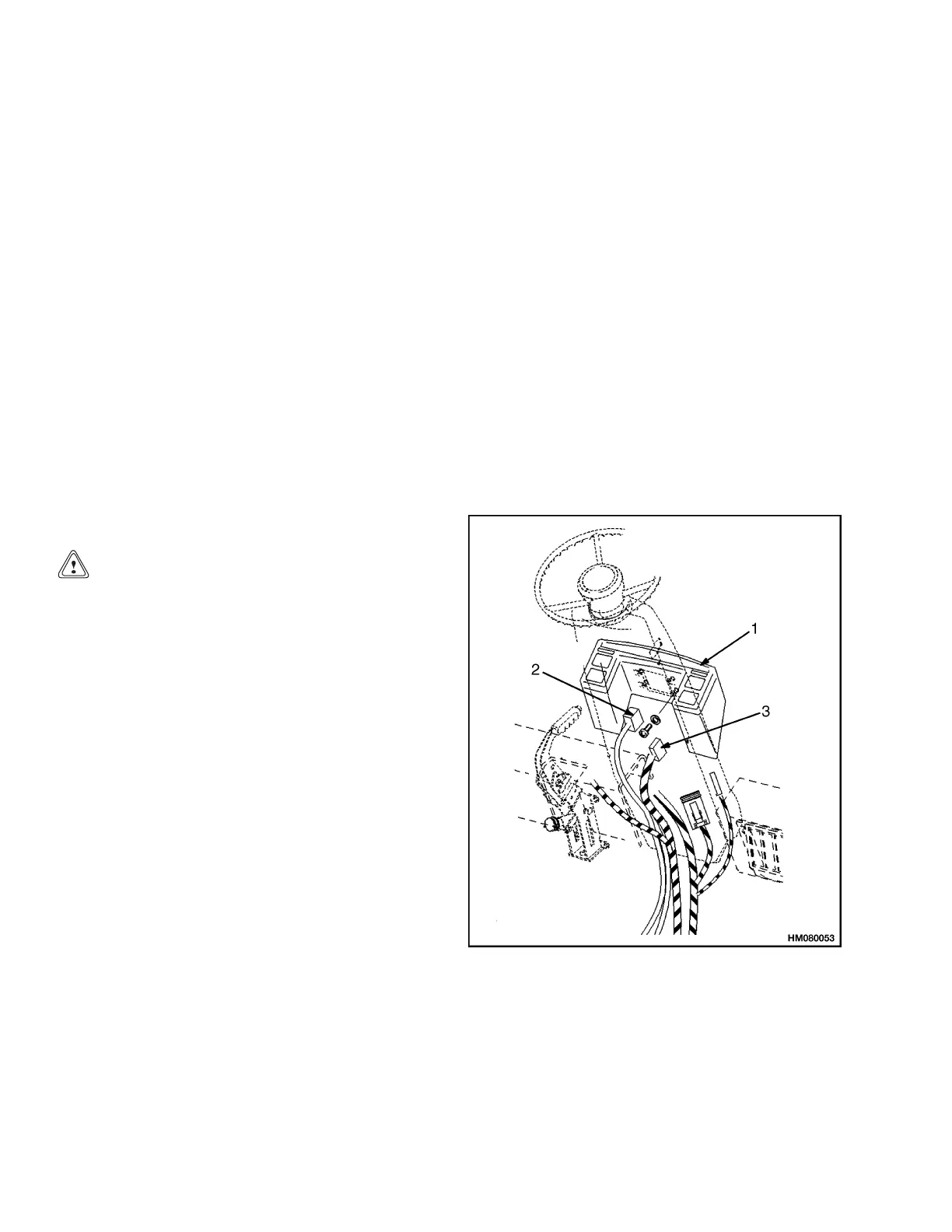
2. For older model instrument cluster panels, dis-
connect the two wiring harnesses at the instru-
ment cluster. See Figure 5, Figure 7, and Fig-
ure 8. For newer model instrument cluster pan-
els, disconnect the 24-pin and 6-pin pig tail con-
nections and the ground wire at the steering col-
umn. See Figure 6 and Figure 8.
3. Remove screws that hold instrument cluster to
steering housing.
1. INSTRUMENT CLUSTER
2. WIRIN
G HARNESS (24-PIN CONNECTOR)
3. WIRING HARNESS (6-PIN CONNECTOR)
Figure 5. Instrument Cluster Mounting (Older
Model Cluster Panels)
12
 Loading...