2200 SRM 514 Description
Table 1. Instrument Cluster, Internal Combustion (Continued)
Item
No.
Item Function
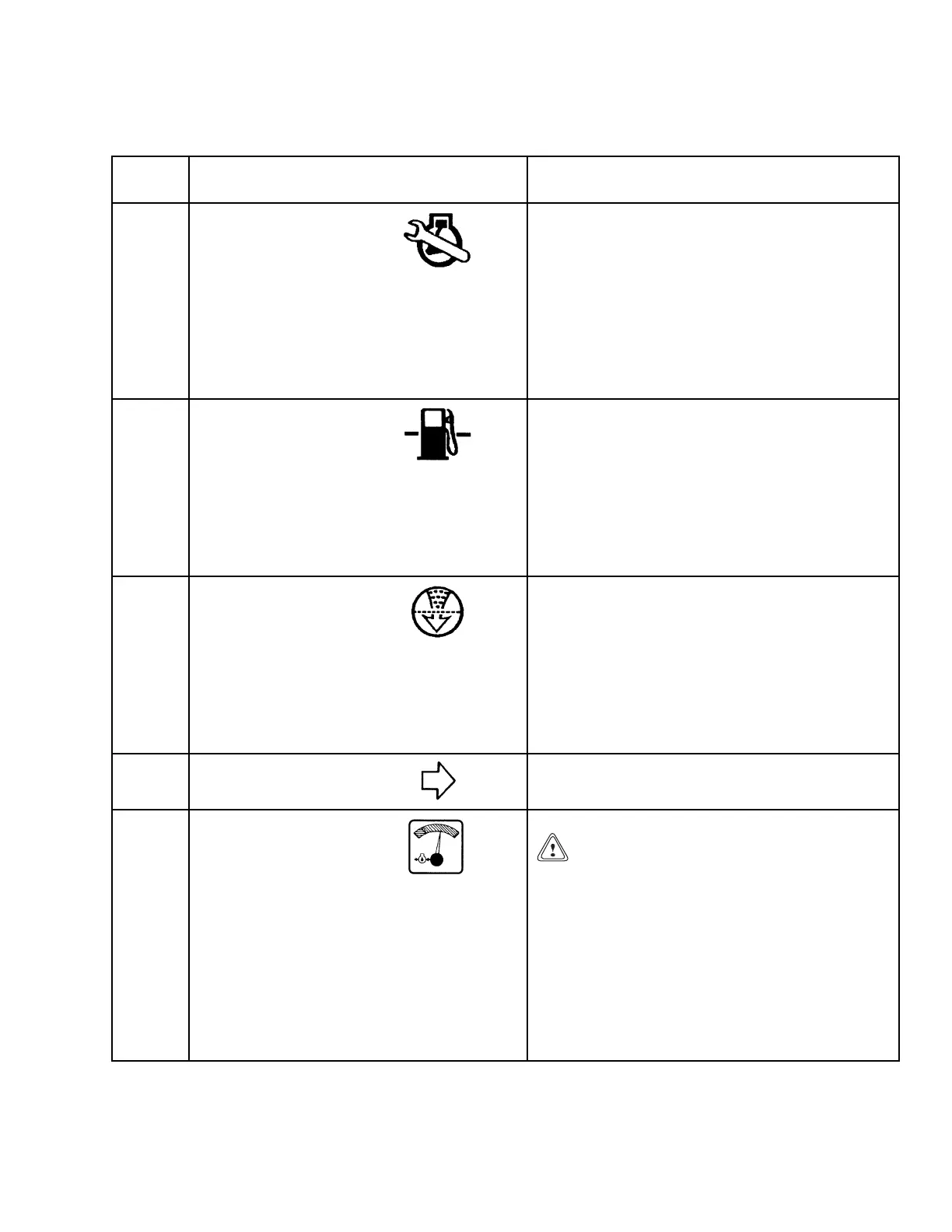
13
Malfunction
Indicator Lamp
(Only on units with
GM 3.0L engine
or low emissions
exhaust system)
The light will be ON when the key is in the ON
position and the engine is not running. This light
will illuminate when the ECM computer senses a
fault in the operation of the engine. If the engine
will start, the operation of the engine will not be
correct until the fault is corrected. If this light is
ON when the engine is running, a trained service
person must make repairs and adjustments. See
the Electronic Engine Control section for your
lift truck model.
14
Indicator Light,
Low LPG Fuel
Level
The red light is ON when the key is in the
START position and must go OFF when the
engine is running. If the light is ON when the
engine is running, the fuel level in the tank is
low. The sending unit for the light is in the fuel
line at the fuel filter. If the warning light does
not work, check the wiring or replace the sending
unit or light. To check the wiring, see the service
manual section for Diagrams.
15
Indicator Light, Air
Filter Restriction
The red light is ON when the key is in the START
position and must go OFF when the engine is
running. If the light is ON whentheengineis
running, the air cleaner has a restriction and
needs cleaning. The sending unit for the light is
in the canister for the air filter. If the light does
not work, check the wiring or replace the sending
unit or light. To check the wiring, see the service
manual section for Diagrams.
16
Right-Hand Turn
Indicator (Optional)
The light is on when the turn indicator lever is in
the right turn position.
17
Engine Oil Pressure
Gauge
CAUTION
Do not continue to operate the lift truck
when the gauge indicates low oil pressure
(needle in the red area).
Thisgaugeindicatesthepressureoftheoilin
the engine. During normal operation, the gauge
needle will be in the green area. The sending unit
for the gauge is in the engine block. If the gauge
does not work, check the wiring or replace the
sending unit or gauge. To check the wiring, see
the service manual section for Diagrams.
5