Hyundai Elevator Co., Ltd. STVF7 SYSTEM
REV.0 2009.11.06
TITLE
File Name :
STVF7 ADJUST MANUAL
STVF7 SERIES
ADJUSTMENT MANUAL
Document Number :
Rev. Commemts :
HELCO-C5-003-01 - 9 - A4(210㎜×297㎜)
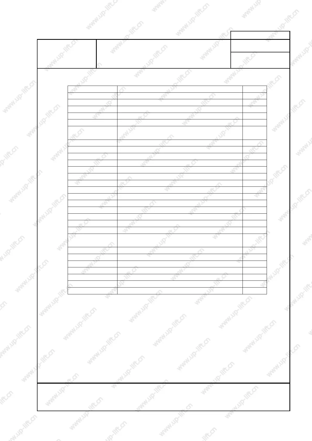
- all connections are referred to electrical diagram "COL 2A,2B,2C,3A,3B,4A"
Item Connection Pin
H2 to PIO board 50p
H3 to PIO board 26p
H9 to inverter CN12 34p
TR1 to transformer
CP2 to CPR1 breaker 2p
CP9, 10, 14, 16,
JUMPER1
to brake coil line
CP5 to power supply DC 5V 2p
CP6 to C/P fan 2p
CP8 to T1B harness 6p
CT3B to governor, BKOP 8p
JT1 to NPR or Jumper(No NPR) 2p
CT1, 2 to final limit switch
CT80 to FR2R 6p
CT6 to buffer, pit 7p
CT66, 67 to limit switch
T1 to CCB-7 board 21p
CT47 to installation remote controller 3p
CT51 to sub brake 5p
CT3A to fire man return switch, parking switch 4p
CT52 to ccs, mt 4p
CT53
to emergency power system,
earthquake sensor, emergency landing system
7p
CT56 to emergency landing system, MFAN 5p
CT58 to X-relay 7p
CT65 to MC1, MC2, BKB contactor 7p
CT55 to MC2, BKB contactor 6p
CT70 to X-relay 2p
CT34 to hall can board 5p
CT16 to remote monitor system 7p
[Table 4. TNP board connection]
 Loading...