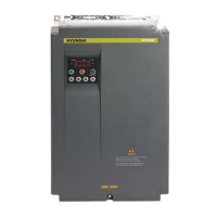
N700 Operating Instructions and Parts Manual 3. Operation
23
3.2.2 Operation setting and the frequency setting from the digital operator
(Remote operator is also same use.)
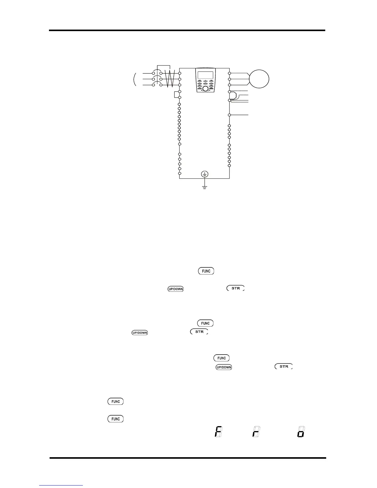
Fig. 3- 2 Setting diagram from the digital operator
(Procedure)
(1) Please make sure that connection is right.
(2) Turn the MCCB on to supply power to the inverter.
(The LED "POWER" on the operator should illuminate)
(3) Set the operator with the frequency setting selection.
① Set F010 as indication code, press the
key once.
(Code values are shown)
② Set 2(OPE KEYPAD) with
key, press the key once to set the frequency
setting for the operator. (Indication code turns back to F010.) [Setting method by OPE-
N7 ]
(4) Set the operator with the operation setting selection.
Set F011 as the indication code, press the
key once.
Set 2(OPE) with
key, press the key once to set the frequency setting for the
operator. (Indication code turns back to F011.)
(5) Set the output frequency
① Set F001 as indication code, by pressing the
key once. (Code values are shown.)
② Set to the desired output frequency with the
key, press the key once to
store it.
(6) Set Monitor mode
① When monitoring the output frequency, set indication code to d001, and press
the
key once.
② Or when monitoring the operation direction, set indication code to d002, press
the
key once.
(In the case of OPE-N7, indication codes are
Forward, Reverse, or Stop. )
DC reactor
Braking Unit
(BRD)
Earth Ground
G
14
N
P
PD
Motor
U
V
W
R
S
T
Short bar
H
O
O2
OI
L
P24
PLC
FM
CM1
FW
1
2
3
4
5
6
7
MCCB
R
S
T
Three phase
Power Supply
13
AL0
8
11
12
AL1
AL2
RN0
RN1
RN2
 Loading...