23
Reference
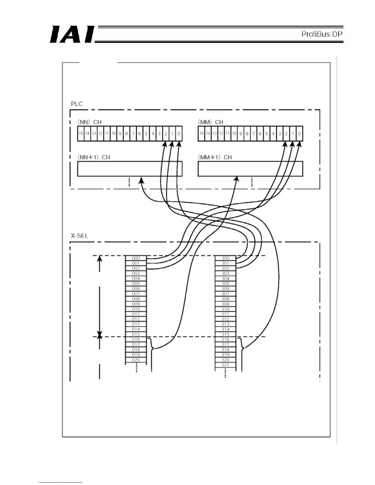
When bit addresses are set in the PLC, port numbers are assigned in units of 16 points,
starting from the channels corresponding to the node address set by the DIP switches.
(This does not apply when a configurator is used.)
(Input) (Output)
(Input) (Output)
Port number Port number
Node address
nn
Node address
nn + 1
The numbers under (NN)/(MM) CH are PLC channel addresses corresponding to node
address nn.
Since node addresses (nn, nn+1, nn+2, and so on) are occupied in accordance with the
numbers of input/output points used, pay attention to prevent duplicate node addresses.
 Loading...
