AFE1_AFE2-1:1
14
Technical specifications
IAR Debug Probes User Guide
I-jet®, I-jet Trace, and I-scope™
* <= 4 ns when the target board is connected
I-jet comes with a 20-pin MIPI connector—0.05 in × 0.05 (1.27 mm x 1.27 mm) pitch—
on the front panel. It includes two cables:
● A 6-inch cable with 20-pin MIPI connectors on both ends for the Cortex-M targets
with 20-pin MIPI headers. Pin 7 on each end is keyed with a white plug.
● A 6-inch cable with a 20-pin MIPI connector on one side (to connect to I-jet), and a
10-pin MIPI connector on the other side for connection to Cortex-M targets with
10-pin headers. Pin 7 on the 20-pin end is keyed with a white plug. A red stripe on
the cable indicates pin 1 (VTref).
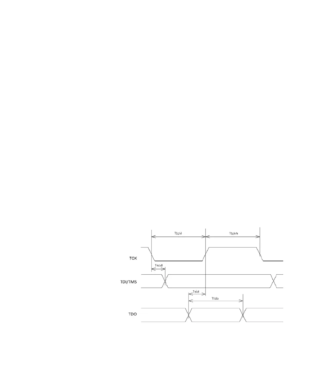
JTAG TIMING SPECIFICATION
This figure shows the JTAG timing and parameters:
Target power measurement resolution ~160 uA
Target power measurement speed up to 200 ksps (kilo samples per second)
JTAG voltage range (auto-sensing) 1.65 V to 5.5 V
JTAG VTref measurement resolution ~2 mV
Current draw from VTref < 50 uA
JTAG clock rise/fall time (TCK) <= 2 ns*
Clock fall time <= 2 ns*