AFE1_AFE2-1:1
16
Technical specifications
IAR Debug Probes User Guide
I-jet®, I-jet Trace, and I-scope™
Version, production date, and serial number can be found on the backside of the probe.
Note: In IAR Embedded Workbench, choose I-jet>EmuDiag to start the EmuDiag
application where you can diagnose the connection between the host computer, the
probe, and the board.
TARGET INTERFACE
This section contains descriptions of pinout, signals, and connectors. The following
cables are described in detail:
● The JTAG/SWD - MIPI-20 cable
● The JTAG/SWD - MIPI-10 cable
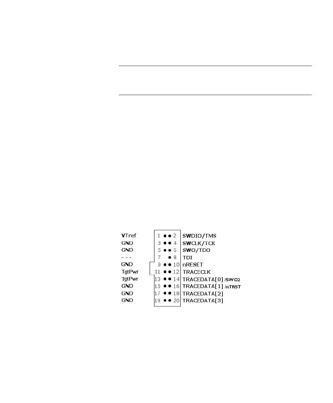
The JTAG/SWD - MIPI-20 cable
I-jet comes with a 6-inch cable with 20-pin MIPI connectors on both ends for the
Cortex-M devices with 20-pin MIPI headers. Pin 7 on each end is keyed with a white
plug:
The mating connector for a target board has the pitch size 0.05 in (1.27 mm). You can,
for example, use part number SHF-110-01-L-D.
Version B Added extra RAM to the SWO FIFO buffer to improve
SWO performance on older, slower PCs.
Optional board current measurement resolution at 16.3 uA
instead of 163 uA on I-jet Version A.
June 2017
Version Change specification Date
Table 2: I-jet versions (Continued)